Repair LineLazer IV 250SPS Self-Propelled Line Striper 3A2593B EN For the application of line striping materials. For professional use only. For outdoor use only. Not for use in hazardous locations or explosive atmospheres. Maximum Operating Speed: 10 mph (16 kph) Maximum Operating Pressure: 3300 psi (22.8 MPa, 228 bar) IMPORTANT SAFETY INSTRUCTIONS Read all warnings and instructions in this manual and the engine manual. Save these instructions.
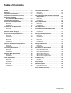
Table of Contents Models . . . . . . . . . . . . . . . . . . . . . . . . . . . . . . . . . . . 3 Warnings . . . . . . . . . . . . . . . . . . . . . . . . . . . . . . . . . 4 Component Identification . . . . . . . . . . . . . . . . . . . . 7 Component Identification (Controls) . . . . . . . . . . . 8 Grounding Procedure (For Flammable Materials Only) . . . . . . . . . . . 9 Pressure Relief Procedure . . . . . . . . . . . . . . . . . . . 9 Ground Drive Belt Replacement . . . . . . . . . . . . . 10 Removal . .
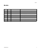
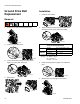
Models Models Model Guns Pressurized Bead System 24F307 2 No LLIV 250SPS (North America, Latin America, Asia Pacific) 24K960 1 No LLIV 250SPS (Latin America, Asia Pacific) 24K961 1 No LLIV 250SPS (Europe) 24K962 2 No LLIV 250SPS (Europe) 24M608 1 No FieldLazer G400 (North America) 16V470 1 Yes, 1 Tank LLIV 250 SPS (Latin America, Asia Pacific) 16V471 1 Yes, 1 Tank LLIV 250 SPS (Europe) 16V473 2 Yes, 1 Tank LLIV 250 SPS (North America, Latin America, Asia Pacific) 16V474
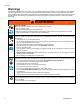
Warnings Warnings The following warnings are for the setup, use, grounding, maintenance, and repair of this equipment. The exclamation point symbol alerts you to a general warning and the hazard symbols refer to procedure-specific risks. When these symbols appear in the body of this manual or on warning labels, refer back to these Warnings. Product-specific hazard symbols and warnings not covered in this section may appear throughout the body of this manual where applicable.
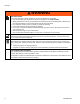
Warnings WARNING PRESSURIZED ALUMINUM PARTS HAZARD Use of fluids that are incompatible with aluminum in pressurized equipment can cause serious chemical reaction and equipment rupture. Failure to follow this warning can result in death, serious injury, or property damage. • Do not use 1,1,1-trichloroethane, methylene chloride, other halogenated hydrocarbon solvents or fluids containing such solvents. • Many other fluids may contain chemicals that can react with aluminum.
Warnings WARNING BATTERY SAFETY The battery may leak, explode, cause burns, or cause an explosion if mishandled. • Only use the battery type specified for use with the equipment. See Technical Data. • Battery maintenance must only be performed or supervised by personnel knowledgeable of batteries and the required precautions. Keep unauthorized personnel away from battery. • Do not dispose of battery in fire. The battery is capable of exploding. • Follow local ordinances and/or regulations for disposal.
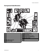
Component Identification Component Identification 1. 16. 15. 14. 11. 17. 2. 13. 12. 10. 3. F OF ON 9. 8. 4. 5. 7. 6.
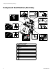
Component Identification (Controls) Component Identification (Controls) 5. 4. 3. 6. 2. 7. 1. 1 on off 2 8. 1 9. 2 10. 11.
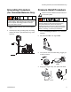
Grounding Procedure (For Flammable Materials Only) Grounding Procedure Pressure Relief Procedure (For Flammable Materials Only) This equipment must be grounded to reduce the risk of static sparking. Static sparking can cause fumes to ignite or explode. Grounding provides an escape wire for the electric current. 1. Position striper so that the tires are not on pavement. 2. Ground sprayer with grounding clamp. Grounding clamp must attach to grounded object (e.g. metal sign post).
Ground Drive Belt Replacement Ground Drive Belt Replacement Installation 1. Install belt onto pulleys. Removal ti19134a 1. Loosen four screws and remove belt cover. 2. Tighten tensioning bolt to move two pulleys apart and tighten belt to proper tension (see table). ti19132a ti19128a Ground Drive Belt Tension Recommendations 2. Loosen two hold-down bolts.
Oil Reservoir Belt Replacement Oil Reservoir Belt Replacement Installation 1. Replace belt. Removal ti19149a NOTE: Ground drive belt must be removed before oil reservoir belt can be replaced (see page 10). 2. Tighten two adjustment bolts evenly and maintain belt alignment. Tighten belt to proper tension (see table). 1. Loosen four hold-down bolts. ti19147a ti19150a 2. Loosen two adjustment bolts to bring pulleys closer together to create slack in the belt.
Hydraulic System Purging Hydraulic System Purging 5. Turn on the Main Power Switch to engage clutch. This equipment stays pressurized until pressure is manually relieved. To help prevent serious injury from pressurized fluid, such as skin injection, splashing fluid and moving parts, follow the Pressure Relief Procedure when you stop spraying and before cleaning, checking, or servicing the equipment. ti18552a 6. Slowly pull forward/reverse control lever in forward and reverse directions 10 times.
Ground Drive Pump Replacement Ground Drive Pump Replacement 5. Remove nut (3) and disconnect tie rod (40) underneath pump (63). 6. Remove two mounting bolts (82) and washers (55) to remove pump (63) from bracket. Installation This equipment stays pressurized until pressure is manually relieved.
Oil Reservoir Pump Replacement Oil Reservoir Pump Replacement This equipment stays pressurized until pressure is manually relieved. To help prevent serious injury from pressurized fluid, such as skin injection, splashing fluid and moving parts, follow the Pressure Relief Procedure when you stop spraying and before cleaning, checking, or servicing the equipment. 6. Remove pulley from pump. Remove four screws and pump from reservoir cover. ti19672a Installation 1.
Oil Reservoir Pump Replacement 4. Turn pressure control knob clockwise until seated. 7. Slide cable sleeve up and tighten screw. ti19145a 8. Connect three hydraulic hoses to fittings on oil reservoir. Replace oil filter. ti23905a 5. Turn hydraulic pump pressure control clockwise until seated then counterclockwise 1/6 turn. ti23906a ti24913a ti19139a ti23906a 9. Install and tension Oil Reservoir Belt (page 11) and Ground Drive Belt (page 10). 6. Install cable and tighten set screws. 10.
Hydraulic Gun Manifold Replacement Hydraulic Gun Manifold Replacement 6. Label wire harnesses GUN 1 and GUN 2. Disconnect two wire harnesses from solenoids. Gun 2 Gun 1 Removal ti19161a 1. Remove tank lid and siphon tube. 7. Label gun cables Gun 1 and Gun 2. Disconnect gun cables from actuators. Gun # ti19159a ti24916a 8. Use a needle-nose pliers to remove gun cables from bracket. ti24196a 2. Remove tank from unit. 3. Remove six screws from front shield. ti19667a 9.
Hydraulic Gun Manifold Replacement 10. Disconnect manifold tubes at manifold. 11. Remove two mounting bolts and slide hydraulic manifold down and out from unit. 4. Push Gun 1 and Gun 2 gun cables into bracket. NOTE: Be sure to connect Gun 1 cable to the hole in the bracket closest to center of sprayer. 5. Connect Gun 1 and Gun 2 cables to actuators. ti19159a ti19162a 6. Connect two wire harnesses to solenoids. NOTE: Be sure to connect Gun 1 to coil closest to center of sprayer. Installation Gun 2 1.
Paint Pump Replacement Paint Pump Replacement 5. Use hammer to loosen pump jam nut (106). 6. Slide down retainer (104) and remove pin (105). 7. Unscrew and remove paint pump (107). This equipment stays pressurized until pressure is manually relieved. To help prevent serious injury from pressurized fluid, such as skin injection, splashing fluid and moving parts, follow the Pressure Relief Procedure when you stop spraying and before cleaning, checking, or servicing the equipment. Installation 1.
Hydraulic Motor Replacement Hydraulic Motor Replacement NOTICE Use a screwdriver to lift pump piston up to gain access to mounting bolts and avoid contact with piston. Contact with pump mounting bolts can scratch and damage the pump piston. This equipment stays pressurized until pressure is manually relieved.
Clutch Replacement Clutch Replacement 7. Remove engine recoil starter and place a screwdriver through the recoil starter cup. Removal 1. Remove Ground Drive Belt, page 10. ti19696a 2. Remove Oil Reservoir Belt, page 11. 3. Remove two hold-down bolts for the ground drive pump bracket. ti19215a 4. Unscrew tensioning bolt from the ground drive pump bracket. ti19697a 8. Remove center bolt (59) and remove clutch (57). 57 ti19131a 58 5. Move ground drive pump assembly aside. 56 60 59 ti19214a 9.
Clutch Replacement Installation 4. Install pulley (61) and torque three screws (81) to 10 ft-lb (13 N•m). 1. Install spacer (56) and key (60) onto crankshaft. Slide clutch (57) onto crankshaft. 57 61 56 81 60 58 ti19216a 59 ti19214a 5. Install recoil starter onto engine. 2. Align clutch and wire in bracket. ti19704a 6. Connect clutch to wire harness. ti19211a 3. Install heavy washer (58) and bolt (59) onto crankshaft. Torque bolt to 45 +/- 5 ft-lb (61 +/- 7 N•m).
Engine Replacement Engine Replacement 5. Disconnect choke cable. Removal 1. Remove Clutch, see page 20. ti19185a 2. Disconnect all wires from engine. 6. Tie knot in rope by recoil starter to prevent rope from being pulled into recoil starter. 7. Take rope handle apart and untie knot in recoil starter handle. ti15307a 3. Remove air filter cover, element and base. ti19188a 8. Pull rope through rope guide. 9. Remove four mounting bolts from engine. ti19187a 10. Remove engine.
Engine Replacement Installation d. Tighten screw on hex-shaped pivot. 1. Install engine voltage regulator below engine mounting plate with two screws. Connect regulator to wire harness. e. Verify proper operation of engine choke. ti19686a 6. Install throttle cable. a. Place speed lever to high speed. b. Insert “Z” bend wire into hole furthest from pivot. ti19706a 2. Install engine and tighten four mounting bolts and nuts. c.
Touch-Pad Replacement Touch-Pad Replacement Removal Installation 1. Remove six screws and control shroud. 1. Apply touch-pad to sheet metal. 2. Connect ribbon cable from touch-pad at display board. ti19098a 2. Disconnect ribbon cable from touch-pad at display board. ti19910a 3. Install control shroud with six screws. ti19910a 3. Peel off touch-pad and remove adhesive from sheet metal.
Control Board, Toggle Switches and Display Replacement Control Board, Toggle Switches and Display Replacement 7. Remove six screws and control shroud. Removal 1. Remove Fuse to disconnect battery, page 29. 2. Remove tank lid and siphon tube. ti19098a 8. Remove two screws and splash shield. ti24916a ti24916a 3. Remove tank from unit. ti19701a 9. Remove two toggle switch nuts from control panel. 4. Use wrench to remove six screws from front shield. ti19702a ti19163a 10.
Control Board, Toggle Switches and Display Replacement 11. If replacing the toggle switches loosen two screws holding the ferrite core. Disconnect cable and remove toggle switch board. ti20133a 13. If replacing control board, disconnect all wires from control board. Remove eight mounting screws and remove control board. ti19198a ti20135a ti20136a ti19199a 12. If replacing the display, remove two screws holding the ferrite core to toggle switch bracket.
Control Board, Toggle Switches and Display Replacement 5. Feed toggle switches through control panel and install two toggle switch nuts. 10. Install front shield and tighten six screws. ti19691a 6. Install Fuse, see page 29. Check control, switches and display. ti19200a 11. Install tank, lid and siphon tube. 7. Install splash shield with two screws. ti19705a 8. Install control shroud with six screws. ti24917a ti24917a 12.
Battery Replacement Battery Replacement Installation 1. Install battery. NOTICE To reduce the risk of shorting the battery, always connect NEGATIVE (black wire) last. Removal 1. Remove tank lid and siphon tube. 2. Connect red wire to positive (+) and black wire to negative (-) posts of the battery. ti24916a ti24916a 2. Remove tank from unit. 3. Use wrench to remove six screws from front shield. ti24920a 3. Install battery hold down strap. ti19163a 4. Remove front shield from unit. 5.
Fuse Replacement Fuse Replacement 1. Remove fuse cover. 2. Use needle-nose pliers to remove old fuse and inspect it for open circuit. 3. If fuse is open, a wire has shorted to the frame or auxiliary lighting requires too much power. Check wiring or reduce auxiliary lighting before replacing fuse. 4. Use needle-nose pliers to install new fuse. 5. Replace cover.
Forward/Reverse Cable Replacement Forward/Reverse Cable Replacement 6. At the handlebar, remove locknut (3) and ball joint (40) from handlebar forward/reverse lever. Remove ball joint (40) from cable (148) and save if not replacing. Loosen two nuts on cable (148) and remove from bracket. 40 3 Removal 1. Remove tank lid and siphon tube. 148 ti19699a ti24916a 7. At the ground drive pump, remove locknut (3) and ball joint (40) from ground drive pump.
Forward/Reverse Cable Replacement Installation 3. Install cable (148) into handlebar bracket and tighten two nuts. Install ball joint (40) onto cable. Install ball joint into handlebar forward/reverse lever and tighten locknut (3). 1. Install new cable (148) by following same route as old cable is being removed. 2. At ground drive pump bracket (62), install cable (148) in bracket slot and tighten two nuts.
Steering Cable Replacement Steering Cable Replacement 7. Apply parking brake. Raise front wheel off the ground and support frame on two jack stands. Removal 1. Remove tank lid and siphon tube. ti18550a 8. At the handlebar, remove locknut (3) and ball joint (40) from handlebar. Remove ball joint (40) from cable (48) and save if not replacing. Loosen two nuts on cable (48) and remove from bracket. 3 40 ti24916a ti24916a 48 2. Remove tank from unit. 3. Use wrench to remove six screws from front shield.
Steering Cable Replacement Installation 1. Install new cable (48) by following same route as old cable is being removed. 5. Install ball joint (40) onto cable (48) and match threads on other side of handlebar. Install ball joint (40) into handlebar and tighten locknut (3). 3 2. At front wheel, adjust front nut on cable (48) to match the threads on the other side of front fork. Install cable (48) into frame bracket and tighten rear nut. 40 48 Adjust to match other side of front fork ti19685a 3.
Front Wheel Replacement Front Wheel Replacement Installation 1. Insert two spacers (36) into wheel (35) and slide into fork (34). Removal 1. Apply parking brake. Raise front wheel off ground and support frame on two jack stands. 34 39 37 36 ti20125a ti19693a 36 2. Remove locknut (39) from axle bolt (37) and remove axle bolt (37) from fork (34). 35 2. Insert axle bolt (37) through fork (34), spacers (36) and wheel (35). 3. Tighten locknut (39) onto axle bolt (37).
Parking Brake Service Parking Brake Service Installation 1. Install lever (14) with pin (B) and clip (13). Removal 2. Use screwdriver to install spring (15). 16 1. Remove tire, wheel hub, and fender. See Wheel Motor Removal, page 36. 16 A 2. Remove clips (13) from three pins (A). Remove pins and levers. A A 16 16 10 A 17 10 17 A 10 15 14 A ti19684a 13 A 15 15 B B 13 B B 13 17 A 15 14 17 14 14 A A 10 ti19684a 13 3. Use screwdriver to remove spring (15).
Rear Wheel and Wheel Motors Rear Wheel and Wheel Motors Wheel Motor Removal 1. Place jack under frame near wheel and raise jack. Rear Wheel Removal 2. Remove four lug nuts (22) and wheel (16). 1. Set LineStriper on blocks so wheels are off ground. 16 22 ti18587a 2. Remove four lug nuts (22) and wheel (16). ti18589a 3. Remove pin (56), castle nut (21b) and wheel hub (22b). Wheel hub may require a wheel puller; not supplied by Graco.
Rear Wheel and Wheel Motors Wheel Motor Installation 2. Remove tank from unit. 1. Connect two hydraulic hoses (112) to wheel motor (21a) and insert wheel motor (21a) into frame (1). 3. Use wrench to remove six screws from front shield and remove front shield from unit. 2. Install distance sensor (4) and clamp (5) with screw (6). 6 5 4 19 79 21a ti19163a 112 22b 56 ti18584a 21b 4. Place jack under frame near pump-side wheel and raise jack. 5. Remove four lug nuts (22) and wheel (16). 16 78 3.
Rear Wheel and Wheel Motors Installation 5. Install wheel (16) and four lug nuts (22). 1. Install wheel sensor (4) and clamp (5) with screw (6). 16 6 22 5 4 ti18589a 6. Lower jack. 7. Install front shield with six screws. ti19099a 2. Connect wheel sensor connector to wire harness. ti19200a ti19328a 8. Install tank and siphon tube. 3. Verify sensor is working by turning on the main power switch and press SETUP to display the MEASURE screen. 4.
Troubleshooting Troubleshooting General Problem Engine pulls hard Engine will not start High engine speed at no load Machine will not drive Engine operates, but displacement pump does not operate 3A2593B Repair Cause Excessive hydraulic load. Main power switch is on. Solution Turn main power switch OFF. Engine is out of gas. Refill gas tank. See engine manual. Fuel shut-off lever is OFF. Move fuel shut-off lever to ON position. Engine switch is OFF. Turn engine switch ON.
Troubleshooting Problem Displacement pump operates, but output is low on upstroke Displacement pump operates but output is low on downstroke and/or on both sides Pump is difficult to prime Low stall or run pressure shown on display Excessive paint leakage into throat packing nut Fluid is spitting from gun 40 Cause Solution Piston ball is not seating. Service piston ball. See manual 309277. Piston packings are worn or damaged. Replace packings. See manual 309277.
Troubleshooting Problem Excessive leakage around hydraulic motor piston rod wiper Sprayer overheats Excessive hydraulic pump noise Display does not turn on Gallon (liter) counter not adding fluid volume Distance not adding properly (MEASURE mode will be inaccurate and speed will be wrong) Mils not calculating Pressure control knob does not rotate Pressure control knob rotates freely with no pressure change Gun does not trigger Gun triggering is slow 3A2593B Repair Cause Solution Piston rod seal
Troubleshooting Problem Cause Solution AUTO Mode Line spacing is not accurate Gun does not trigger Wrong line pattern loaded Reload the correct pattern. Machine not calibrated Perform calibration routine (see Operation manual). See Gun Does Not Trigger, page 41. PARKING LAYOUT Mode Gun does not apply dots Gun selector switch is OFF Turn gun selector switch ON. Dot size setting is too small Increase dot size. Pressure is too low Increase pressure to 1000 psi.
3A2593B Repair 223 112 4 189 238 237 224 TO GROUND LUG BLACK RED GUN 1 GUN 2 225 189a 391 221 187 214c 214e 150 TO GROUND LUG 214b TO GROUND LUG 222 214f 214t 134 WHITE RED RED RED BLACK 253 TO ENGINE YELLOW WHITE BLACK RED BLACK 220 RED BLACK RED RED YELLOW BLACK BLACK BLACK 54a YELLOW 214h TO GROUND LUG 57 54 Wiring Diagram Wiring Diagram ti19065a 43
Wiring Diagram Wiring Parts List Ref.
3A2593B Repair 196 3YY 366 198 197 109 108 370 372 371 366 189C 194 189A 189B 193 2 189 111 110 166 22 191 63 309 333 190 327 166 2 3XX 320 ti24923a 3XX Hydraulic Diagram Hydraulic Diagram 45
Hydraulic Diagram Hydraulic Parts List Ref.
Notes Notes 3A2593B Repair 47
Graco Standard Warranty Graco warrants all equipment referenced in this document which is manufactured by Graco and bearing its name to be free from defects in material and workmanship on the date of sale to the original purchaser for use. With the exception of any special, extended, or limited warranty published by Graco, Graco will, for a period of twelve months from the date of sale, repair or replace any part of the equipment determined by Graco to be defective.