
User's Manual

Installation
3A2100C 5
Installation
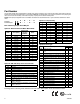
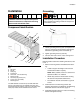
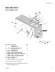
Component Identification
Key:
A Site glass
B Fill cap
CDrain plug
D Pump blank
E Drive shaft - (with woodruff key)
F Mounting holes
G Accessory plug (heater port)
H Pump (not on all models)*
J Mounting screw
*The GBL7500 Box Lubricator Pump and GBL Shaft Rota-
tion/Low Level Alarm Pump are available from Graco. See
Accessories/Other Accessories, page 12 for information about
these pump models and the related instruction manual.
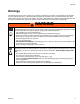
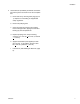
Grounding
1. Loosen grounding screw (a) (FIG. 2) and place one
end of a 12 gauge (1.5mm) minimum ground wire
between the grounding screw and washer (b).
2. Tighten grounding screw (a) securely.
3. Connect other end of wire to a true earth ground.
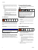
Installation Procedure
Reference letters used in the following instructions, refer
to F
IG. 1.
1. Select a mounting surface that satisfies the follow-
ing:
• Is able to support the weight of the reservoir
and fluid when filled to capacity.
NOTE: When possible, mount to a surface that
experiences little or no vibration.
• Allows easy access to the lubricator for filling
the reservoir and periodic maintenance.
• The lubricator must be connected to a ground
source.
2. Install reservoir to the mounting surface. See
mounting hole layout in the Reservoir and Mounting
Dimension section of this manual, page 14.
3. Install bolts through holes (F) in reservoir mounting
bracket and tighten securely.
Modular box lubricators are not approved for use in
hazardous locations or explosive atmospheres
unless all accessories, components and wiring
meet all local and national codes.
FIG. 1
ti17757
A
B
C
D
E
F
G
H
J
The equipment must be grounded to reduce the risk
of static sparking. Static sparking can cause fumes to
ignite or explode. Grounding provides an escape wire
for the electric current.
FIG. 2
a
b