
User's Manual


Installation
Electrical Co
nnections
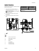
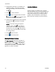
Install per Graco Control Drawing 16M169, in Manual
332013. See also Figure 1.
1. Connect main
power supply cord (E, not
supplied) th
rough strain relief to terminals L and
N on the power
supply unit.
Note: Use ei
ther strain relief (5) or (6), depending
on the size o
fthecord.
2. Connect pow
ercordgroundwiretoground
terminal bl
ock.
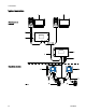
3. Connect IS
power cable (F) per the following
table.
Power Cable Leads Barrier Connection
Brown (power) Connector 1
Blue (common
)
Connector 2
Glossy Black (ground) and Black (drain) connect to
ground block.
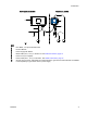
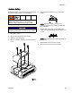
Figure 1
K
EY
E
Inbound AC Power Cord
F
Power Cable to Informer
W
Ground Wires
XBarrier
Y
Ground Block
5
Strain Relief Fitting
6
Strain Relief Fitting
3A2040E 13