
User's Manual


Installation
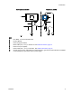
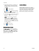
Grounding
The equipment must be grounded to reduce the
risk of static sparking and electric shock. Electric
or static sparking can cause fumes to ignite or
explode. Improper grounding can cause electric
shock. Grounding provides an escape wire for the
electric current.
NOTE: The Informer does not provide 500 VAC
isolation through the coupling nuts on the enclosure.
The associated apparatus and the field apparatus
cable shields must not be connected to the Informer
coupling nuts.
1. Power Supply 1
6M167: Connect the ground wire
from the power
supply to a true earth ground.
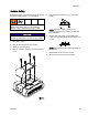
2. Informer Modu
le: Connect a ground wire and
clamptothes
crew on the top of the bracket.
Connect the o
ther end to ground. In an IS
system, the I
nformer also is grounded by
connection
to the grounded power supply.
3. Flow Meter:
Follow the instructions in manual
308778 (G30
00) or manual 313599 (Coriolis) to
ground the fl
ow meter and check its electrical
grounding
continuity.
4. Fluid Supp
ly: Ground the fluid supply unit.
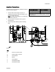
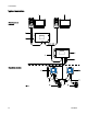
Cable Connections
Port Description
Connection
1
Fiber Optic Receiver Red Lead from TX on Fiber Optic Converter (PN 16K465) orfrom
Port 6 on another Informer (or ProControl 1KE)
2
Fiber Optic Transmitter Black Lead to RX on Fiber Optic Converter (PN 16K465) or to Port
5 on another Informer (or ProControl 1KE)
3 Power
From Power Supply
4
Digital Input/Output To/From Meter and to Light Tower (accessory)
5
Fiber Optic Reciever Black Lead from Port 2 on another Informer (or ProControl 1KE)
6
Fiber Optic Transmitter Red Lead to Port 1 on another Informer (or ProControl 1KE).
1
2
3A2040E