
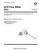
User's Manual


Installation
3A1657F 9
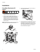
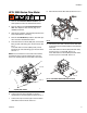
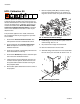
8. Connect B (Blue) flow meter and fittings to fluid
manifold. See F
IG. 12.
9. Connect the supply and return hoses from the appli-
cator to the corresponding fittings.
10. Connect the 4-pin connector of the flow meter data
cable to the flow meter.
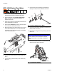
11. Route the flow meter data cable as shown in
F
IG. 13.
NOTE: For NVH - Modular systems, route the flow
meter data cable as shown in F
IG. 7, page 7.
12. Connect the other end to the fluid control module
installed in the electrical enclosure.
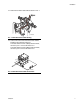
If the data cable is for the A (Red) side flow meter,
connect to port 1 on the FCM. See F
IG. 14.
If the data cable is for the B (Blue) side flow meter,
connect to port 2 on the FCM. See F
IG. 14.
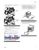
13. Install token into the FCM and turn the system
power on. Once the software installation is com-
plete, remove the token.
FIG. 12: B (Blue) Flow Meter Installation
FIG. 13: Flow Meter Data Cable Routing
1:1 Ratio
24:1 or 16:1
Ratio
FIG. 14: Flow Meter Data Cable Connections
FIG. 15: Token Installation
ti17014a
ti17219a