
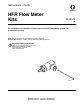
User's Manual


Installation
6 3A1657F
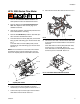
HFR: 6000 Series Flow Meter
1. Perform HFR Pressure Relief Procedure. See
HFR operation manual for detailed instructions.
2. Perform dispense valve Pressure Relief Proce-
dure. See dispense valve manual, page 3, for
detailed instructions.
3. Verify all air, hydraulic, and material pressures have
been relieved before continuing.
4. Perform HFR Shutdown procedure. See HFR oper-
ation manual for detailed instructions.
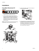
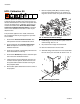
5. Remove all fittings from the outlet ports on the front
of the fluid manifold. See F
IG. 4. Note which side
each fitting is from to make sure they are installed
on the correct side later.
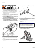
6. Connect swivel fitting (302) to fluid manifold. See
F
IG. 5.
7. Connect fittings (303 and 304) to flow meter (301).
See F
IG. 5.
8. Connect flow meter and fittings to swivel fitting
already connected to fluid manifold. See F
IG. 5.
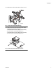
9. Connect the flow meter assembly to the fluid mani-
fold as shown. See F
IG. 6.
10. Re-install the fittings that were previously removed.
See F
IG. 6.
11. Connect the 4-pin connector of the flow meter data
cable to the flow meter. See F
IG. 6.
FIG. 4: Remove Fluid Manifold Fittings
ti17015a
FIG. 5: Connect Fittings to Flow Meter
NOTICE
Make sure to install the fittings in the correct mate-
rial lines. Failure to do so will result in material
cross-contamination of the fittings and material
hoses.
FIG. 6: Flow Meter Installation
ti17016a
302
303
301
304
ti17017a