
User's Manual


Flow Meter Connector Pinout
3A1657F 19
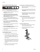
Flow Meter Connector Pinout
The system utilizes a 5-pin CAN connection for commu-
nication with the flow meter. If a non-Graco flow meter is
used the flow meter signal must be converted to the fol-
lowing 5-pin connection.
NOTE: The connection shown is the FCM connector,
not the CAN cable pins.
1 +10-30 VDC Supply
2 Signal out
3Ground
4 Not Used
5 Not Used
Maintenance
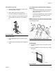
Install Upgrade Token
NOTE: The Motor Control Module, Fluid Control Mod-
ule, and Temperature Control Module connection to the
system is temporarily disabled during the installation of
upgrade tokens.
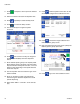
To install software upgrades:
1. Use correct software token stated in the table. See
Graco Control Architecture
™
Module Programming
manual for instructions.
NOTE: Upgrade all modules in the system to the
software version on the token, even if you are
replacing only one or two modules. Different soft-
ware versions may not be compatible.
All data in the module (System Settings, USB Logs,
Recipes, Maintenance Counters) may be reset to
factory default settings. Download all settings and
user preferences to a USB before the upgrade, for
ease of restoring them following the upgrade.
See manuals for locations of specific GCA compo-
nents.
The software version history for each system can be
viewed in the technical support section at
www.graco.com.
FIG. 22: FCM 5-pin Connector Input
2
3
4
1
5
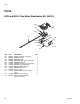
Token Application
16G407 Ratio Monitoring (Flow Meters):
- Fluid Control Module
FIG. 23
ti12334a1