
User's Manual


Calibration
3A1657F 15
For Probler P2 Gun Only --
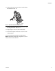
a. Disconnect both material lines at the gun. See
gun manual listed on page 3.
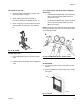
b. Attach material lines to fluid manifold (1)
included in calibration kit 24J326. See F
IG. 19.
c. Place o-rings (2) in correct location then attach
fluid manifold to the base (3) of the calibration
kit.
For MD2 Valve Only --
a. Use an adjustable wrench to remove the static
mixer.
b. Install the ratio check adapter onto the dispense
valve.
For L-Head, S-Head, GX-7 DI, and GX-16 Dispense
Valves Only --
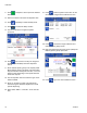
• If calibrating the A (Red) side, close the B (Blue)
valve on the fluid manifold. Make sure the A
(Red) valve is open.
• If calibrating the B (Blue) side, close the A (Red)
valve on the fluid manifold. Make sure the B
(Blue) valve is open.
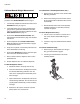
NOTE: The valves on the fluid manifold are closed when
pointing to the side, as shown in F
IG. 20. They are open
when pointing forwards.
All Assemblies --
9. Turn the main power switch on the HFR to the ON
position.
10. Press the ADM Power On/Off button (CA) to enable
the system.
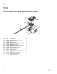
FIG. 19: Kit 24J326
ti17022a
FIG. 20: Fluid Manifold Valves - shown closed
FIG. 21: Fluid Manifold Valves
A
ti17021a
B
ti17021a
CA