
User's Manual
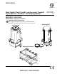
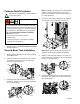
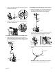

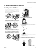
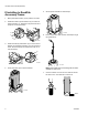
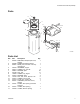
Table Of Contents
2 3A1302D
Pressure Relief Procedure
Follow the Pressure Relief Procedure whenever
you see this symbol.
1. Relieve pressure. See Pressure Relief Procedure
in manual 3A1214.
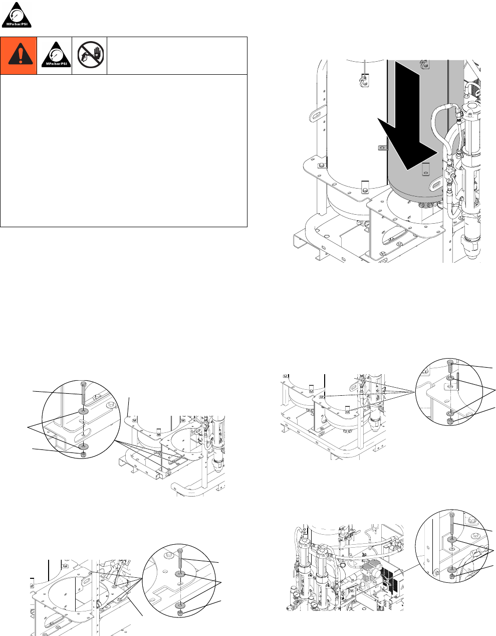
Second Bead Tank Installation
1. Place bead tank mounting bracket (2) into position
on RoadPak frame.
2. Install three bolts (16) and washers (17) on bottom
of bracket (2). Thread nuts (15) onto bolts and
torque to 15 ft-lb (20.3 N•m).
3. Install four bolts (18) and washers (17) to top of
bracket (2). Thread nuts (15) onto bolts and torque
to 15 ft-lb (20.3 N•m).
NOTE: If installing to accessory frame kit (24H585)
install four bolts (18) and washers (17) to top of
bracket (2). Thread nuts (15) onto bolts and torque
to 15 ft-lb (20.3 N•m).
4. Use hoist (or other lifting equipment) to lift bead tank
(1) and lower it into tank mounting bracket (2).
NOTE: Make sure bead tank is positioned with air
regulator inlet facing toward inside of RoadPak.
5. Install four bolts (18) and washers (17) at each cor-
ner bead tank mount. Thread nut (15) onto bolts and
torque to 27 ft-lb (36.6 N•m).
6. Install bolt (12) and washers (13) into center bead
tank mount. Thread nut (14) onto bolt and torque to
15 ft-lb (20.3 N•m).
The system pressure must be manually relieved to pre-
vent the system from starting or spraying accidentally.
Fluid under high pressure can be injected through the
skin and cause serious injury. To reduce the risk of an
injury from injection, splashing fluid, or moving parts,
follow the Pressure Relief Procedure in manual
3A1214 whenever you:
• are instructed to relieve the pressure
• stop spraying
• check or service any of the system equipment
• install or clean the spray tip
ti16797a
16
17
15
2
ti16796a
18
17
15
2
ti16798a
ti16799a
18
17
15
ti16800a
12
13
14