
User's Manual
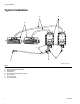
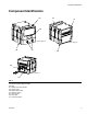
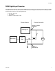
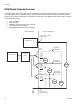
Table Of Contents
I/O Setup
8 3A1149D
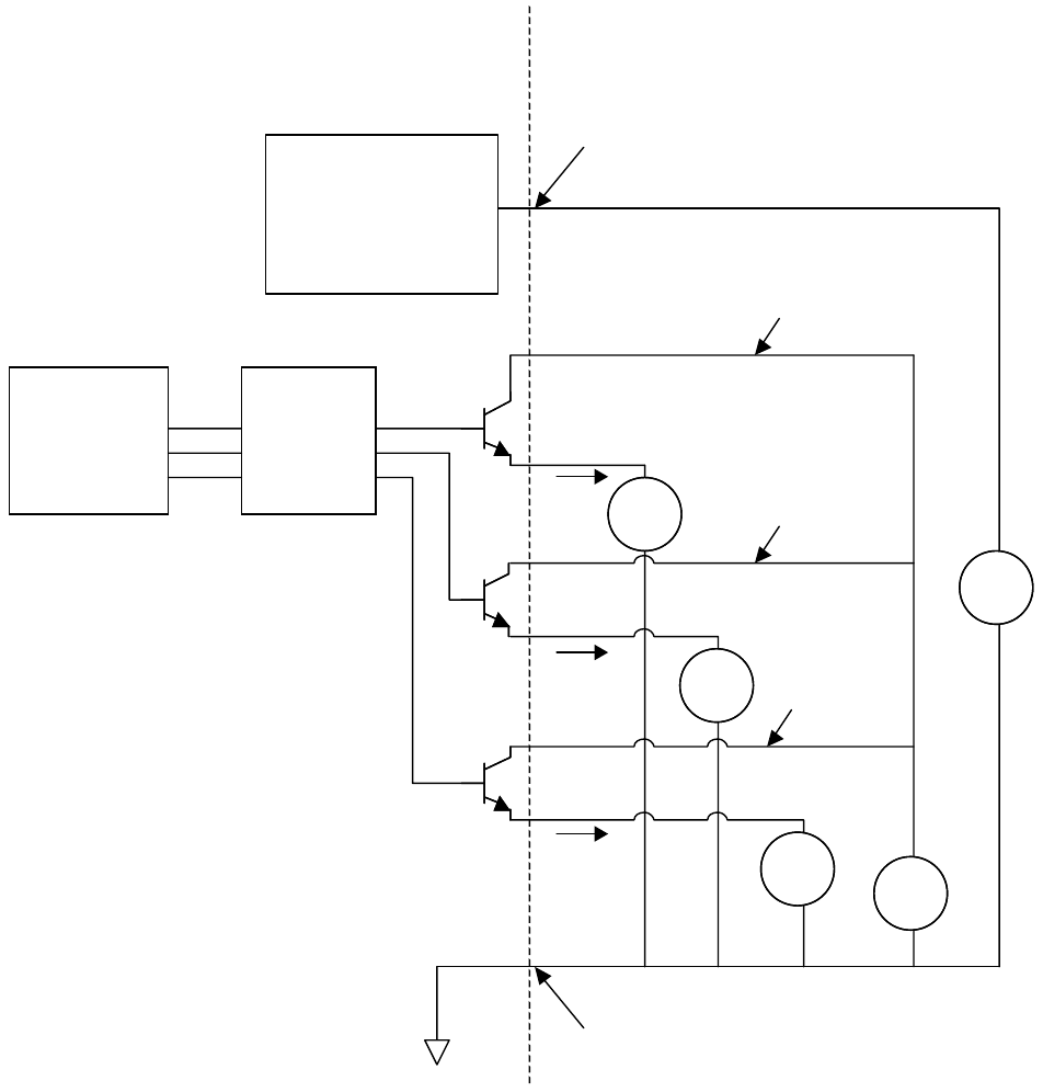
DGM Digital Outputs Overview
The digital outputs function only when power is supplied to pins 27, 68, and 69 and there is a ground connection to
pin 70. The digital output is rated at 0-30 VDC, and requires an NEC Class 2 power supply connected to pin 27 for
supply bank 1, pin 69 for supply bank 2, and pin 68 for supply bank 3. The DGM provides optical isolation as shown
in the following illustration.
• Pins: 9-20, 28-39
• Type: Sourcing
• Maximum continuous current output: 350 mA
(sourced from customer supply)
• Recommended continuous current: 100 mA
Microcontroller
Discrete Gateway
Optical
Isolator
Digital
Output
1-8
Isolated Logic ICs
24VDC24VDC
D-Sub Pin 51 (Isolated
Logic Supply)
D-Sub Pin 70
(Isolated Ground)
Customer Automation
24VDC24VDC
LOADLOAD
LOADLOAD
LOADLOAD
Digital
Output
9-16
Digital
Output
17-24
Digital Input
Supply Bank 1
Digital Input
Supply Bank 2
Digital Input
Supply Bank 3
D-Sub
Pin 27
D-Sub
Pin 69
D-Sub
Pin 68