
User's Manual
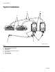
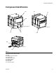
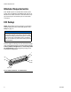
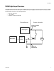
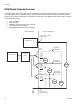
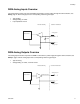
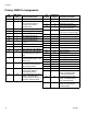
Table Of Contents
Module Requirements
6 3A1149D
Module Requirements
Each DGM requires a 9-30 VDC NEC Class 2 power
supply. This is supplied to the DGM through pins 27, 51,
68, 69 on the D-Sub connection. Ground from this sup-
ply should only be connected to pin 70 of the D-Sub
connection.
I/O Setup
NOTE: Each DGM is set as the primary or secondary
DGM by setting the rotary switch (AG) position. See
Setup on page 14.
See the Digital and Analog I/O Overview sections begin-
ning on the following page for I/O setup details. See the
Primary DGM Pin Assignments and Secondary DGM
Pin Assignments sections beginning on page 10 for
individual pin assignments.
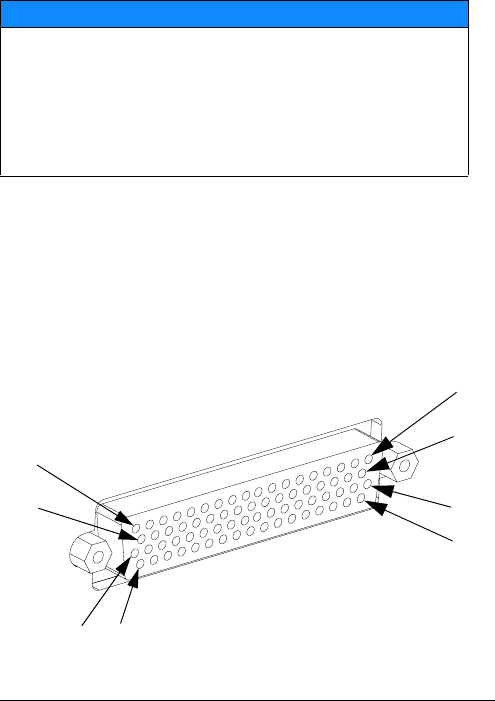
NOTICE
To avoid ground loops and noise immunity issues, do
not ground the shield of the D-sub connector cable.
The shield is already grounded through the mounting
screw on the base of the DGM. If using a breakout
board, do not make any connections to the pins with
ground symbols.
F
IG. 3: D-sub Connector - Pin References
1
20
21
40
60
7859
39