
User's Manual
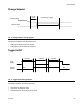
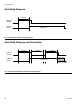
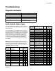
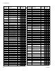
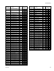
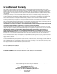
Table Of Contents
Troubleshooting
3A1149D 31
Troubleshooting
Diagnostic Information
7
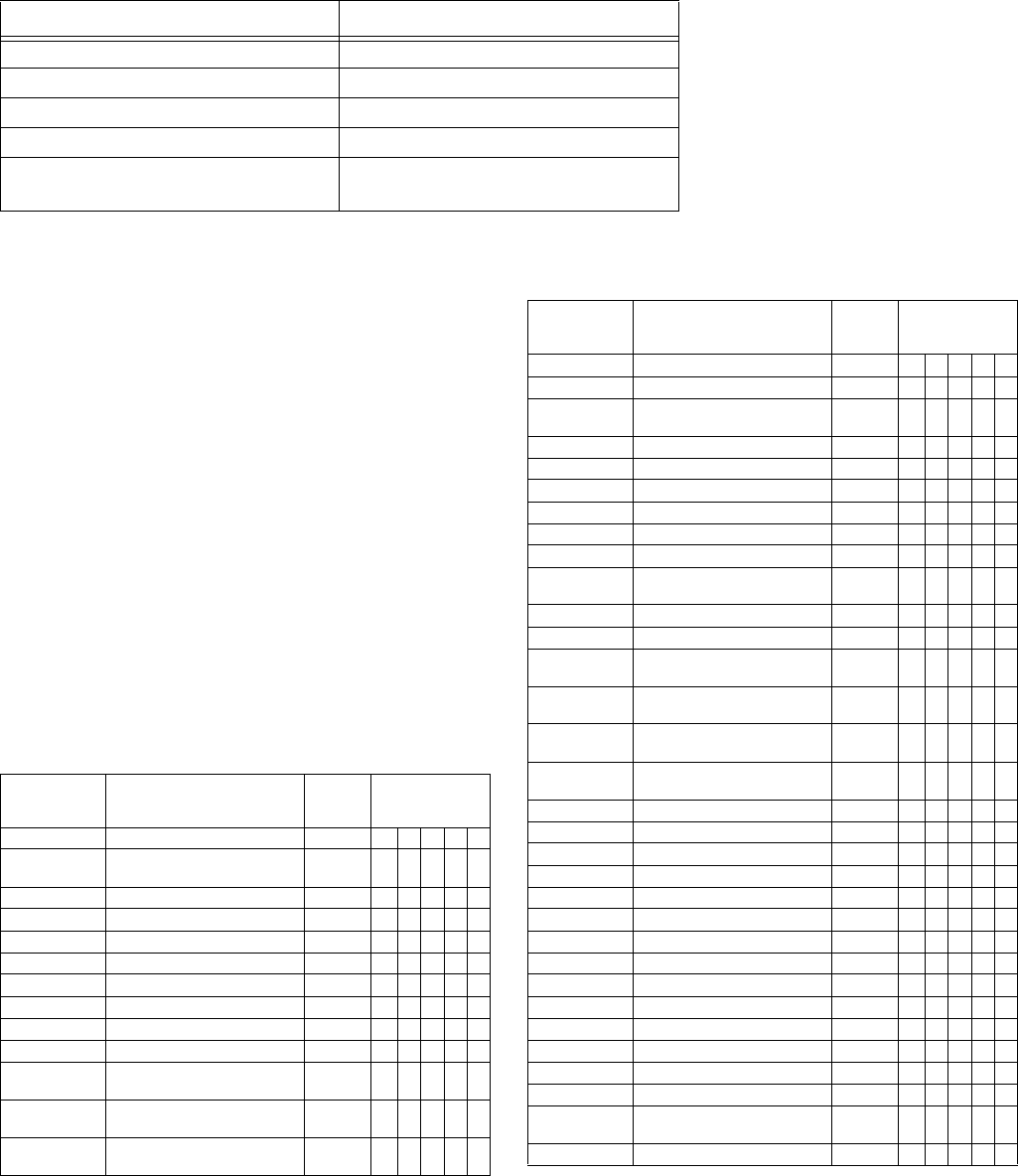
Fault Code Bit Pattern Table
This is an 8-bit pattern indicating the current error num-
ber in the system. The bit pattern is accompanied by the
Error Present bit.
If the PLC displays error messages, the PLC program-
mer should translate the bit pattern to the corresponding
descriptive string. See the following table to translate the
fault code bit pattern to a descriptive string. The Error
Number column is used for reference to aid the PLC
programmer in translating from fault code bit pattern to
error string. When error number 255 with bit pattern
“11111111” occurs the user should check the ADM for
error details.
NOTE: This manual is available at Graco.com. To pre-
vent having to manually re-type these error codes and
strings into your PLC program, go to Graco.com and
retrieve the electronic version of this manual then copy
the following table from the PDF.
Module Status LED Signal Diagnosis
Green on System is powered up
Yellow Internal communication in progress
Red solid DGM hardware failure, replace DGM
Red flashing fast Uploading software
Red flashing slow Token error, remove token then
re-install software token
Fault Code
Bit Pattern
(Bit 7 --> Bit 0)
Error String
Error
Number
Error Code
Shown on the
ADM
00000000 No Active Errors 0 0 0000
00000001
Motor Temp. Shutdown B
(Blue)
1AT4N1
00000010 Motor Temp. Cutback B (Blue) 2 V T 3 N 1
00000011 Oil Temp. Shutdown B (Blue) 3 A T 4 H 1
00000100 Oil Temp. Cutback B (Blue) 4 D T 3 H 1
00000101 Low Oil Level B (Blue) 5 A M B H 1
00000110 Motor Over Current B (Blue) 6 A A 4 H 1
00000111 Motor Over Current B (Blue) 7 A A 4 N 1
00001000 Motor Over Current B (Blue) 8 A A 4 M 1
00001001 Motor Over Current B (Blue) 9 A A 9 C 1
00001010
Motor Control High Temp. B
(Blue)
10 A T 4 C 1
00001011
Motor Control Overvoltage B
(Blue)
11 A V 4 H 0
00001100
Motor Control Undervoltage B
(Blue)
12 A V 1 H 1
00001101 Motor Encoder Fault B (Blue) 13 A W B H 1
00001110 Motor Controller Fault B (Blue) 14 D W M H 1
00001111
Low Motor Performance B
(Blue)
15 V M B N 1
00010000 High Motor Speed B (Blue) 16 A W K H 1
00010001 B (Blue) Pump Failed to Move 17 D N 4 A 1
00010010 Invalid Setpoint Request 18 D W S C 0
00010011 Small Shot Request 19 D B 9 C 0
00010100 Pressure Imbalance 20 A P 4 D 0
00010101 Pumps Not Defined 21 A D S C 0
00010110
Invalid Learn Mode Data B
(Blue)
22 D D 5 A 1
00010111 Invalid Weight Cal. Data 23 D 0500
00011000 B (Blue) Position Sensor Fault 24 A D 6 A 1
00011001
A (Red) Pressure Sensor
Fault
25 A P 6 A 1
00011010
B (Blue) Pressure Sensor
Fault
26 A P 6 B 2
00011011
B (Blue) Setpoint Not
Reached
27 D D 1 A 1
00011100
B (Blue) Setpoint Not
Reached
28 D D 2 A 1
00011101 B (Blue) Setpoint Exceeded 29 D D 4 A 1
00011110 B (Blue) Setpoint Exceeded 30 D D 3 A 1
00011111 A (Red) Pressure Shutdown 31 A P 4 A 1
00100000 B (Blue) Pressure Shutdown 32 A P 4 B 2
00100001 B (Blue) Pump Not Parked 33 D D F A 1
00100010 B (Blue) Pump Failed to Stall 34 D F 7 D 1
00100011 Invalid Gel Timer Definition 35 D W S D 0
00100100 A (Red) Pump Cavitation 36 D D D A 1
00100101 B (Blue) Pump Cavitation 37 D D D B 2
00100110 Pressure Terminated Cal. 38 V P 9 A 1
00100111 Pressure Terminated Cal. 39 V P 9 B 2
00101000 Flow Terminated Cal. 40 V D A A 1
00101001 Thermal Pressure Rise 41 D P 4 0 0
00101010 Setpoint Outside Cal. Range 42 V 0 9 C 1
00101011
A (Red) Motor Temp. Shut-
down
43 A T 4 N 2
00101100 A (Red) Motor Temp. Cutback 44 V T 3 N 2
Fault Code
Bit Pattern
(Bit 7 --> Bit 0)
Error String
Error
Number
Error Code
Shown on the
ADM