
User's Manual

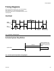
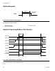
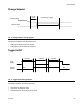
Table Of Contents
Timing Diagrams
3A1149D 25
Timing Diagrams
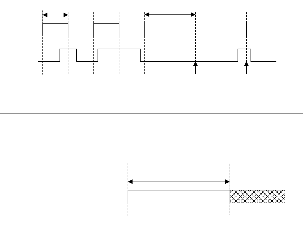
Once the last line has been set in any of the following
timing diagrams, a 10 mS settle time should be
observed to allow the PLC and DGM hardware to reach
a steady state.
Heartbeat
Activate System Stop Button
FIG. 6: Heartbeat Timing Diagram
F
IG. 7: Activate System Stop Button Timing Diagram
3 Sec
DGM
Heartbeat
PLC
Heartbeat
Heartbeat
Timed out
Heartbeat
Resuming
6 Sec
>185 mS
System Stop
System Disabled until
turned back on through
dispense request key or
ADM.