
User's Manual
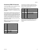
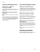

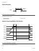
Table Of Contents

Operation
3A1149D 21
Secondary DGM I/O Overview
The secondary DGM is used for controlling and monitor-
ing the status of the heaters and chillers.
NOTE: The HFR has a total of 8 possible conditioning
zones that can be implemented in the system. In any
given instance, a maximum of 4 conditioning zones can
be enabled.
Each temperature conditioning item is assigned a zone
number. Most temperature conditioning bits relate to a
zone number rather than to a specific temperature con-
ditioning item’s name. Knowing the correct zone number
is important for desired machine operation. The zone
numbers are always assigned in the order shown in the
following table. Going down the list, the first enabled
item is zone 1, the second is zone 2, the third is zone 3,
and the fourth is zone 4.
NOTE: There will be less than four zones if less than
four temperature conditioning items are installed or
enabled on the ADM.
The following is an example of a system with Tank
Heater A (Red), Inline Heater B (Blue), Hose Heater B
(Blue), and Chiller A (Red) enabled and shows the
assigned zone numbers for each.
See the Secondary DGM Digital Outputs section
beginning on page 22 for information about finding out
which temperature conditioning components are
enabled.
Order Temperature Conditioning Item
1 Tank Heater, A (Red)
2 Tank Heater, B (Blue)
3 Inline Heater, A (Red)
4 Inline Heater, B (Blue)
5 Hose Heater, A (Red)
6 Hose Heater, B (Blue)
7 Chiller, A (Red)
8 Chiller, B (Blue)
Zone Order Temperature Conditioning Item
1 1 Tank Heater, A (Red)
2 Tank Heater, B (Blue)
3 Inline Heater, A (Red)
2 4 Inline Heater, B (Blue)
5 Hose Heater, A (Red)
3 6 Hose Heater, B (Blue)
4 7 Chiller, A (Red)
8 Chiller, B (Blue)