
User's Manual
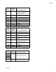

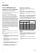
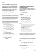
Table Of Contents

Operation
3A1149D 17
Digital Inputs 9-15: Select Shot Bits
The shot selection bits are used to select one of the 100
different defined shots. The user must use the ADM to
define each shot. The DGM will use a 7-bit pattern to
select one of the shots.
The machine must be in Shot mode to select a shot.
Digital Inputs 12-15 have alternate functionality in Oper-
ator, Shot and Standby modes. Below are their alternate
functions:
Digital Input 12 becomes:
(used in Operator, Shot, and Standby modes)
• Enable Dispensing: Keep this bit low when not
selecting a shot. If this bit is high during a dispense
request or park pump request, the request will be
ignored. If this bit goes high during a dispense the
system will go into Disabled mode.
Digital Input 13 becomes:
(used in Disabled mode)
• Enable ADM: Toggle this bit to enable the ADM.
Digital Input 14 becomes:
(used in Standby mode)
• Dispense Valve Open: While this bit is pulled high
the dispense valve will remain open. When it is
pulled low the dispense valve will be closed.
Digital Input 15 becomes:
(used in Standby mode)
• Set/Release Dispense Valve Lock: Toggle this bit
high to lock or unlock the dispense valve in Standby
Mode.
Digital Input 16
The function of this bit is based on the selected operat-
ing mode:
• Shot Mode: Sets the shot number. To use, set the
Shot Selection Bits to the desired bit pattern then
toggle this bit low then high then low to change the
shot. After toggling this bit, the PLC programmer
should verify that the current shot number matches
the request.
• Operator Mode: Sets the dispense pressure or
flow. To use, set Analog Input 1: Set Pressure/Set
Flow to the voltage for the corresponding desire flow
or pressure. After 185 mS of settling, toggle this bit
to set the new analog value. The PLC programmer
should check Digital Output 4 to make sure the set-
point was accepted.
See the Primary DGM Analog Inputs section on
page 19 for analog input voltage calculation.
• Standby Mode: Hold the bit high to park the pump.
Use the Digital Output 24 to verify the pump has
successfully parked. Release the bit when the pump
is successfully parked.
Shot Selection Bit Pattern
Shot
Selected
Digital
Input
9
Digital
Input
10
Digital
Input
11
Digital
Input
12
Digital
Input
13
Digital
Input
14
Digital
Input
15
0000000Not Defined
0000001 Shot 1
0000010 Shot 2
0000011 Shot 3
…
1100100Shot 100
1100101Not Defined
…
1111111Not Defined