
User's Manual
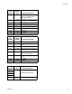
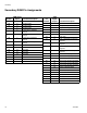
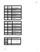

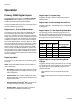
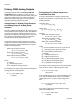
Table Of Contents

Operation
16 3A1149D
Operation
Primary DGM Digital Inputs
See DGM Digital Inputs table in the Primary DGM Pin
Assignments section beginning on page 10 for pin
numbers associated with each bit description.
The primary DGM allows the PLC to control and monitor
the HFR’s dispensing properties.
Digital Input 1: PLC to DGM Heartbeat
The external control device (PLC) and DGM will each
have Heartbeat inputs and outputs. The heartbeat
serves as a verification that both devices are communi-
cating. The PLC does not need to implement any timers
to regulate the period of the heartbeat. To successfully
complete a heartbeat, the PLC must match the output
state of the DGM heartbeat. This can happen as soon
as the PLC detects the change in output state, or within
6 seconds of detecting a change in heartbeat state. If
the PLC does not match the output state of the DGM
after 6 seconds, the DGM will disable the system. This
will only happen once, and the HFR can be reactivated
and operated from the ADM. The DGM will not accept
any more requests until the heartbeat resumes between
the PLC and DGM.
Digital Input Bit 2
The function of this bit is based on the selected operat-
ing mode:
NOTE: The Enable Dispensing bit must be pulled low
prior to dispensing.
• Shot Mode: Toggle this bit high to dispense a single
shot. Toggle the bit in the middle of a shot to termi-
nate the dispense.
• Operator Mode: The machine will dispense while
the bit is pulled high. As soon as the bit falls low, the
dispense terminates.
• Operator Mode with Fusion
®
Gun: Toggle this bit
to stop/start stalling the system to pressure.
• Standby Mode: Toggle this bit high to start/stop
recirculation (recirculation systems only).
Digital Input 3: System Stop
Toggle this bit high to place the dispensing system in
disabled mode.
Digital Input 4: Acknowledge Active Error
Toggle this bit high to acknowledge any errors detected
by the system.
Digital Inputs 5-7: Set Operating Mode Bits
The operating mode is selected through the use of 3
bits. The following table describes the bit pattern to indi-
cate selection of each operating mode. A “1” means the
bit is high and a “0” means the bit is low.
Digital Input 8: Accept Operating Mode
Change
Toggle this bit high while the bit pattern is set to change
the operating mode. After toggling this bit, use the ana-
log output bits to verify the operating mode was suc-
cessfully changed.
* Shot definitions must be configured through the
ADM.
** Night mode settings must be configured through the
ADM.
Operating Mode Bit Pattern
Operating Mode
Digital
Input 5
Digital
Input 6
Digital
Input 7
0 0 1 Disabled
0 1 0 Standby
011 Shot*
1 0 1 Operator
111 Night**