
User's Manual
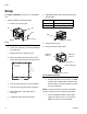
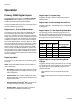
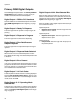
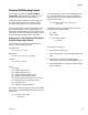
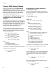
Table Of Contents
Setup
14 3A1149D
Setup
See Typical Installation on page 4 for an assembled
view.
1. Install the DGM in the desired location.
a. Remove access cover (AD).
b. Loosen two screws (AC) and remove DGM (AA)
from base (AB).
c. Attach ground wire to bottom of base.
d. Mount base (AB) in desired location with four
screws. See the following mounting dimensions.
e. Insert screws through top of base and tighten.
f. Insert screw through ground wire and tighten.
g. Mount DGM (AA) on base (AB) with two
screws (C).
h. If applicable, repeat with second DGM.
2. Adjust DGM selector switch (AG) according to the
following table.
3. Install access cover (D).
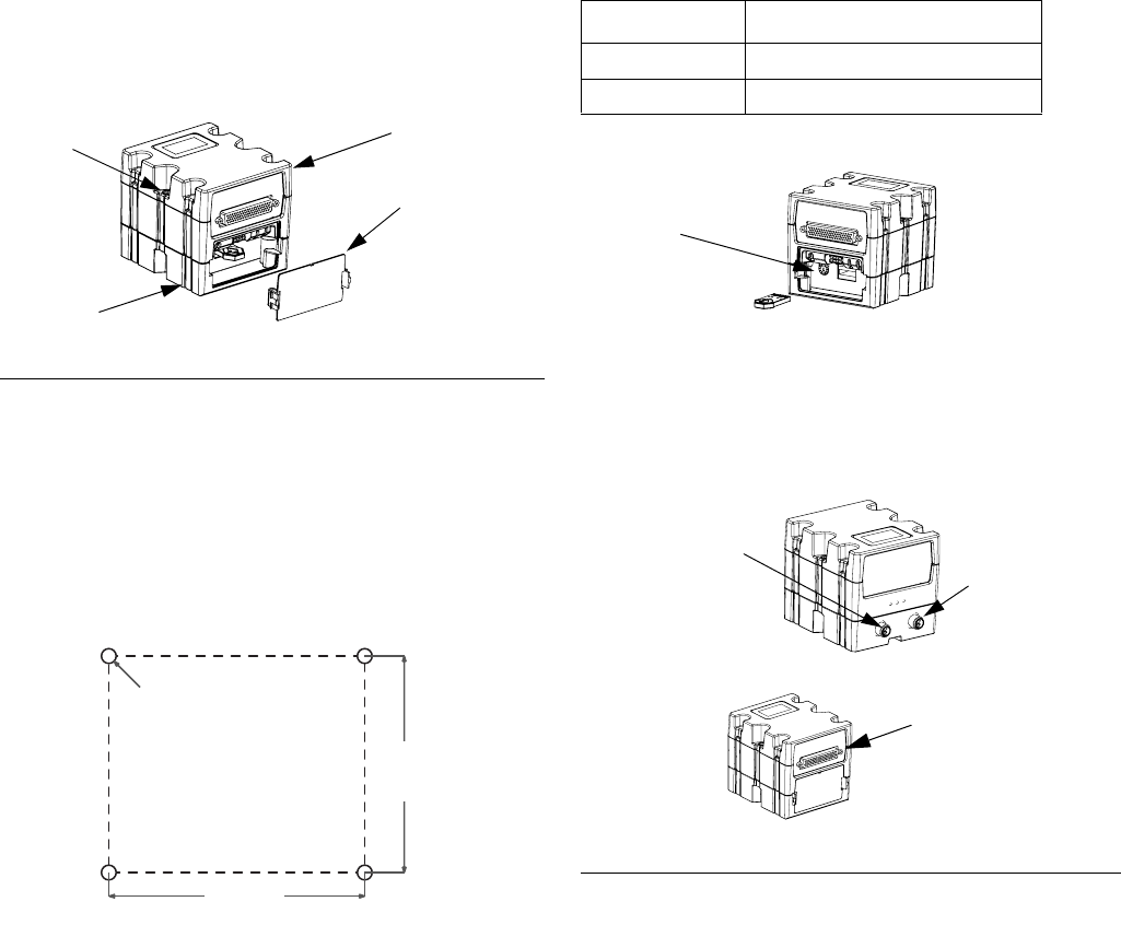
4. Connect CAN and D-Sub cables.
a. Connect CAN cable from Connector 1 on DGM
to ADM or any available CAN connection on the
machine. Attach the ferrite suppressor to DGM
end of the CAN cable.
NOTE: In the previous step if more than one DGM is
used the connection can be made with either DGM.
b. If a second DGM is installed, connect CAN
cable from CAN Connector 1 on the second
DGM to Connector 2 on the first DGM.
F
IG. 4
AD
r_24B681_2B9904_3b
AA
AC
AB
3.25 in.
(82.6 mm)
2.75 in.
(69.9 mm)
#10-32 UNF
(M5 x 0.8)
Setting Zone
1Primary DGM
2 Secondary DGM
F
IG. 5: Cable Connections
AG
r_24B681_2B9904_4b
CAN Con-
nector 1
r_24B681_2B9904_1b
r_24B681_2B9904_2b
D-sub Connector
CAN Con-
nector 2