Instructions HFR™ Discrete Gateway Module Kits 3A1149D ENG For external control of the HFR system. For professional use only. Not approved for use in European explosive atmosphere locations. Single Discrete Gateway Module Kit, 24F843 Dual Discrete Gateway Modules Kit, 24F844 Discrete Gateway Module, 24G830 Important Safety Instructions Read all warnings and instructions in the HFR operation manual 313997. Save all instructions.
Related Manuals Contents Related Manuals . . . . . . . . . . . . . . . . . . . . . . . . . . . 2 Overview . . . . . . . . . . . . . . . . . . . . . . . . . . . . . . . . . . 3 DGM Presence . . . . . . . . . . . . . . . . . . . . . . . . . . 3 Automation Presence . . . . . . . . . . . . . . . . . . . . . 3 Typical Installation . . . . . . . . . . . . . . . . . . . . . . . . . 4 Component Identification . . . . . . . . . . . . . . . . . . . . 5 Module Requirements . . . . . . . . . . . . . . . . . . . . . .
Overview Overview This Discrete Gateway Module (DGM) allows the user to control an HFR through an external control device such as a PLC. The DGM will operate in conjunction with the existing Advanced Display Module (ADM) such that both devices can be used to control the machine. Each HFR can be controlled using up to two DGM’s which will be referred to as the primary and secondary DGM’s. Automation Presence The primary DGM includes a heartbeat monitor.
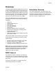
Typical Installation Typical Installation D A B 1 2 C F G E r_24F843_3A1149_1b FIG.
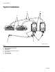
Component Identification Component Identification AA AC AJ AE r_24B681_2B9904_1b AB AF r_24B681_2B9904_2b AD AG r_24B681_2B9904_4b AH FIG.
Module Requirements Module Requirements Each DGM requires a 9-30 VDC NEC Class 2 power supply. This is supplied to the DGM through pins 27, 51, 68, 69 on the D-Sub connection. Ground from this supply should only be connected to pin 70 of the D-Sub connection. I/O Setup NOTE: Each DGM is set as the primary or secondary DGM by setting the rotary switch (AG) position. See Setup on page 14. NOTICE To avoid ground loops and noise immunity issues, do not ground the shield of the D-sub connector cable.
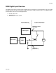
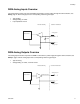
I/O Setup DGM Digital Input Overview The digital inputs function only when power is supplied to pin 51 and there is a ground connection to pin 70. The digital input is rated at 0-30 VDC, and requires an NEC Class 2 power supply connected to pin 51. The DGM provides optical isolation as shown in the following illustration. • • • Pins: 52 – 59, 71-78 Type: Sinking Maximum current draw: 3.
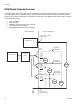
I/O Setup DGM Digital Outputs Overview The digital outputs function only when power is supplied to pins 27, 68, and 69 and there is a ground connection to pin 70. The digital output is rated at 0-30 VDC, and requires an NEC Class 2 power supply connected to pin 27 for supply bank 1, pin 69 for supply bank 2, and pin 68 for supply bank 3. The DGM provides optical isolation as shown in the following illustration.
I/O Setup DGM Analog Inputs Overview The analog inputs function only when the DGM is connected to a power supply through the CAN connection; see Setup, page 14. Each analog input has a corresponding reference (ground) pin.
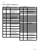
I/O Setup Primary DGM Pin Assignments Pin Number Pin Number DGM Digital Outputs Functional Description 52 1 PLC to DGM Heartbeat 9 1 DGM to PLC Heartbeat 53 2 Dispense Request / Terminate (Shot, Operator modes), or Start/Stop Recirculation (Standby Mode) 10 2 Ready to Dispense 11 3 Dispense in Progress 12 4 Requested Flow Rate/Pressure Setpoint Rejected 13 5 Dispense Mode Selected: Flow (Low) or Pressure (High) 54 3 System Stop 55 4 Acknowledge Active Error 56 5 Set Operatin
I/O Setup Pin Number DGM Analog Inputs 1 1 Set B (Blue) Pump Dispensing Pressure or Combined Dispensing Flow Rate 2 1 - GND Grounding Pin for Analog Input 1 3 2 Not Used 4 2 - GND Not Used 21 3 Not Used 22 3 - GND Not Used 23 4 Not Used 24 4 - GND Not Used Pin Number DGM Analog Outputs Functional Description 40 1 B (Blue) Pump Pressure 41 1 - GND 42 2 43 2 - GND 60 3 61 3 - GND 62 4 Not Used 63 4 - GND Not Used Pin Number Functional Description Grounding Pi
I/O Setup Secondary DGM Pin Assignments Pin Number 12 DGM Digital Inputs Functional Description DGM Digital Outputs 52 1 Set Zone 1 On Pin Number 53 2 Set Zone 2 On 9 1 Not Used 54 3 Set Zone 3 On 10 2 Ready To Dispense 55 4 Set Zone 4 On 11 3 Dispense in Progress 56 5 12 4 Zone 1 On 13 5 Zone 2 On 57 6 14 6 Zone 3 On 58 7 15 7 Zone 4 On 16 8 59 8 17 9 71 9 Accept Zone 1 Setpoint Change Accept Zone 2 Setpoint Change Accept Zone 3 Setpoint Change Accept Zo
I/O Setup Pin Number DGM Analog Inputs Functional Description 1 1 Set Zone 1 Temperature 2 1 - GND 3 2 Grounding Pin for Analog Input 1 Set Zone 2 Temperature 4 2 - GND 21 3 22 3 - GND 23 4 24 4 - GND Pin Number DGM Analog Outputs 40 1 Actual Zone 1 Temperature 41 1 - GND 42 2 Grounding Pin for Analog Output 1 Actual Zone 2 Temperature 43 2 - GND 60 3 61 3 - GND 62 4 63 4 - GND Pin Number Grounding Pin for Analog Input 2 Set Zone 3 Temperature Grounding Pin for Ana
Setup Setup See Typical Installation on page 4 for an assembled view. 1. Install the DGM in the desired location. 2. Adjust DGM selector switch (AG) according to the following table. Setting Zone 1 Primary DGM 2 Secondary DGM a. Remove access cover (AD). AA AC AD AG r_24B681_2B9904_3b AB FIG. 4 r_24B681_2B9904_4b 3. Install access cover (D). b. Loosen two screws (AC) and remove DGM (AA) from base (AB). c. Attach ground wire to bottom of base. 4. Connect CAN and D-Sub cables.
Setup c. Connect D-Sub cable from D-Sub Connector on first DGM to a breakout board or to an external control device. d. If second DGM is installed, connect D-Sub cable from D-Sub Connector on second DGM to a breakout board or to an external control device.
Operation Operation Primary DGM Digital Inputs See DGM Digital Inputs table in the Primary DGM Pin Assignments section beginning on page 10 for pin numbers associated with each bit description. The primary DGM allows the PLC to control and monitor the HFR’s dispensing properties. Digital Input 1: PLC to DGM Heartbeat The external control device (PLC) and DGM will each have Heartbeat inputs and outputs. The heartbeat serves as a verification that both devices are communicating.
Operation Digital Inputs 9-15: Select Shot Bits Digital Input 16 The shot selection bits are used to select one of the 100 different defined shots. The user must use the ADM to define each shot. The DGM will use a 7-bit pattern to select one of the shots. The function of this bit is based on the selected operating mode: • Shot Mode: Sets the shot number. To use, set the Shot Selection Bits to the desired bit pattern then toggle this bit low then high then low to change the shot.
Operation Primary DGM Digital Outputs See DGM Digital Outputs table in the Primary DGM Pin Assignments section beginning on page 10 for pin numbers associated with each bit description. Digital Outputs 18-24: Shot Selected Bits Digital Output 1: DGM to PLC Heartbeat When in Shot mode, these bits are used to form a bit pattern to indicate which shot is selected. See the shot selection bit patterns table in the Primary DGM Digital Inputs section beginning on page 16.
Operation Primary DGM Analog Inputs See Analog Inputs table in the Primary DGM Pin Assignments section beginning on page 10 for pin numbers associated with each bit description. The DGM provides 4 analog inputs and 4 analog outputs. Each analog I/O point has a voltage range of 0-10 VDC. Analog Inputs 2, 3, and 4 are not used.
Operation Primary DGM Analog Outputs See Analog Outputs table in the Primary DGM Pin Assignments section beginning on page 10 for pin numbers associated with each function. Each analog I/O point has a voltage range of 0-10 VDC. The primary DGM analog outputs are used to provide feedback regarding operating pressures and flows. Analog Output 3: B (Blue) Pressure or Combined Flow Rate Analog Output 1: B (Blue) Pump Pressure and Analog Output 2: A (Red) Pump Pressure Volumetric Flow: Fv = 0.
Operation Secondary DGM I/O Overview The secondary DGM is used for controlling and monitoring the status of the heaters and chillers. NOTE: The HFR has a total of 8 possible conditioning zones that can be implemented in the system. In any given instance, a maximum of 4 conditioning zones can be enabled. Each temperature conditioning item is assigned a zone number. Most temperature conditioning bits relate to a zone number rather than to a specific temperature conditioning item’s name.
Operation Secondary DGM Digital Inputs Secondary DGM Digital Outputs Digital Inputs 1-4: Toggle Zone Conditioning On/Off Bits Digital Output 2: Ready To Dispense Pulling this input high turns the zone on. Pulling it low turns the zone off. It is also possible to control the zones using the ADM. Digital Inputs 5-8: Accept Zone Setpoint Change Bits NOTE: This function is only available on 2nd Generation ADM’s.
Operation Secondary DGM Analog Inputs Set Zone Temperature The external control device interfacing with the DGM can use a varying voltage to specify the desired setpoint for the zone. See Secondary DGM Pin Assignments on page 12. To calculate the voltage to use based on the desired temperature in degrees Fahrenheit: Voltage = 0.074 x °F - 4.074 For example, the voltage for 86°F would be: Voltage = 0.074 x 86 - 4.074 = 2.
Operation Secondary DGM Analog Outputs Actual Zone Temperature The analog output voltages indicate the actual temperature of the material at the specified zone. To calculate the temperature in degrees Fahrenheit based on the output voltage: °F = 13.5 x Voltage + 55 For example, if the output voltage is 2.3 then: °F = 13.5 x 2.3 +55 = 86°F To calculate the temperature in degrees Celsius based on the output voltage: °C = 7.5 x Voltage + 12.8 For example, if the output voltage is 2.3 then: °C = 7.5 x 2.
Timing Diagrams Timing Diagrams Once the last line has been set in any of the following timing diagrams, a 10 mS settle time should be observed to allow the PLC and DGM hardware to reach a steady state. Heartbeat 3 Sec 6 Sec DGM Heartbeat PLC Heartbeat Heartbeat Timed out Heartbeat Resuming FIG. 6: Heartbeat Timing Diagram Activate System Stop Button >185 mS System Disabled until turned back on through dispense request key or ADM. System Stop FIG.
Timing Diagrams System Requests >185 mS Performing Request Input Signal FIG. 8: System Requests Timing Diagram The following are system requests: • • Enabling the ADM Acknowledging Errors • Parking the pump Select an Operating Mode or Shot Number 10 mS settle Shot Sel 6 Shot Sel 5 Shot Sel 4 Shot Sel 3 Shot Sel 2 Shot Sel 1 Shot Sel 0 Set New Shot Number >185 mS FIG. 9: Select a Shot Number Timing Diagram The individual lines can change independently in any order.
Timing Diagrams Change Setpoint 10 mS settle Analog Voltage Hold Analog Voltage Set New Value >185 mS FIG. 10: Change Setpoint Timing Diagram This procedure applies to the following functions: • • Changing the dispense pressure setpoint Changing the material temperature setpoint Toggle On/Off >185 mS >185 mS >185 mS Input Signal Feature Activity OFF ON OFF FIG.
Timing Diagrams Shot Mode Dispense >185 mS Dispense Request Dispense Activity Dispensing FIG. 12: Shot Mode Dispense Timing Diagram Shot Mode Dispense and Termination >185 mS >185mS >185mS Dispense Request Dispense Activity Dispensing Remainder of shot not taken. FIG.
Timing Diagrams Operator Mode Dispense >185mS >185 mS Dispense Request Dispense Activity Dispensing FIG.
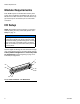
Maintenance Maintenance Install Upgrade Token 4. Press and hold the push-button (M) for three seconds then release. Note: The DGM connection to the system is temporarily disabled during the installation of the upgrade token. NOTE: The LED will flash red until software is done uploading. 5. Remove token (T) when software has successfully uploaded. 1. Ensure system is inactive. 2. Remove access cover (D). 6. Replace access cover (D). 7. Cycle system power.
Troubleshooting Troubleshooting Diagnostic Information 7 Module Status LED Signal Diagnosis Green on System is powered up Yellow Internal communication in progress Red solid DGM hardware failure, replace DGM Red flashing fast Uploading software Red flashing slow Token error, remove token then re-install software token Fault Code Bit Pattern Table This is an 8-bit pattern indicating the current error number in the system. The bit pattern is accompanied by the Error Present bit.
Troubleshooting Fault Code Bit Pattern Error String (Bit 7 --> Bit 0) 32 Error Number Error Code Shown on the ADM Fault Code Bit Pattern Error String (Bit 7 --> Bit 0) Error Number Error Code Shown on the ADM 00101101 A (Red) Oil Temp. Shutdown 45 A T 4 H 2 01100011 A (Red) Chiller Control Fault 99 A A 7 A 00101110 A (Red) Oil Temp.
Troubleshooting Fault Code Bit Pattern Error String (Bit 7 --> Bit 0) Error Number Error Code Shown on the ADM Fault Code Bit Pattern Error String (Bit 7 --> Bit 0) Error Number Error Code Shown on the ADM B (Blue) Hose Low Fluid Temp. 148 10010101 A (Red) Chiller Low Fluid Temp. 149 A T 1 A 7 10010110 B (Blue) Chiller Low Fluid Temp.
Parts Parts 4 5 1 1 1 6 r_24f843_3A1149_1b 11 11 2 2 13 7 3, 9, 10 Ref 1 2 3 4 Part 24B681 289697 24C476 124638 5 6 7 123783 121003 123762 9 10 11 114993 102063 113003 12 13† 14 277674 121901 16D942 * 24F843, Single DGM Kit Description MODULE, GCA, cube, DGM 1 MODULE, cube, GCA, base 1 HARNESS, wire, ground, term, 4 in. 1 CABLE, 78 pin, 2.5 ft, D-sub, male 1 to female BOARD, DGM, 78 pin break out 1 CABLE, CAN, female / female 3.0m 1 CABLE, CAN, 90 x 90, female / female, 0.
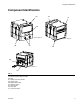
Accessories Accessories Part Description 124415 24E898 24E897 124654 24B861 CAN Cable Extension, 9.8 ft (3.0 m) CAN Cable Extension, 27.9 ft (8.5 m) CAN Cable Extension, 52.5 ft (16.0 m) CAN Splitter, 1 male to 2 female 78 pin d-sub cable; 50 ft (15.2 m), male to female Technical Data Power Requirements . . . . . . . . . . . . . . . . . . . . . . . . . . . . 9-30 VDC NEC Class 2 Weight . . . . . . . . . . . . . . . . . . . . . . . . . . . . . . . . . . . . . . . 14 oz. (0.4 kg) Dimensions. . . . . . .
Graco Standard Warranty Graco warrants all equipment referenced in this document which is manufactured by Graco and bearing its name to be free from defects in material and workmanship on the date of sale to the original purchaser for use. With the exception of any special, extended, or limited warranty published by Graco, Graco will, for a period of twelve months from the date of sale, repair or replace any part of the equipment determined by Graco to be defective.