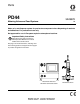
Parts PD44 3A0987K Metering Valves and Feed Systems EN Meter, mix, and dispense system for precise two-component micro-dispensing of sealants and adhesives. For professional use only. Not approved for use in European explosive atmosphere locations. Important Safety Instructions Read all warnings and instructions in PD44 Operation-Maintenance manual 313876. Save all instructions. See page 3 for model information, including maximum working pressure and approvals.
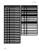
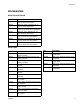
Related Manuals Contents Related Manuals . . . . . . . . . . . . . . . . . . . . . . . . . . . 2 Models . . . . . . . . . . . . . . . . . . . . . . . . . . . . . . . . . . . 3 Product Configurator . . . . . . . . . . . . . . . . . . . . . . . 4 Accessories . . . . . . . . . . . . . . . . . . . . . . . . . . . . . . . 9 Parts . . . . . . . . . . . . . . . . . . . . . . . . . . . . . . . . . . . . 12 Micrometer Drive, 02/2980-1/25 . . . . . . . . . . . . 12 Linear Resistive Transducer Drive . . . . . . . . .
Models Models Max Air Working Pressure psi (MPa, bar) Metal Sleeves Plastic Sleeves CE Approved* Linear Resistive Transducer (LRT) 2000 (14, 138) 100 (0.7, 7) 1200 (8, 83) 400 (2.8, 28) ✔ Micrometer 2000 (14, 138) 100 (0.7, 7) 1200 (8, 83) 400 (2.8, 28) ✔ Motor Driven 2000 (14, 138) 100 (0.7, 7) 1200 (8, 83) 400 (2.
Product Configurator Product Configurator This system can be ordered with many different options as shown in the configurator below.
Product Configurator Code FG Part Low Volume Rod Size NOTE: See code E for first four digits of part number 01 ____01 1.25 mm rod diameter 02 ____02 1.38 mm rod diameter 03 ____03 1.50 mm rod diameter 04 ____04 1.63 mm rod diameter 05 ____05 1.75 mm rod diameter 06 ____06 2.00 mm rod diameter 07 ____07 2.13 mm rod diameter 08 ____08 2.25 mm rod diameter 09 ____09 2.38 mm rod diameter 10 ____10 2.50 mm rod diameter 11 ____11 2.63 mm rod diameter 12 ____12 2.75 mm rod diameter 13 ____13 3.
Product Configurator Code L 1 2 3 4 5 6 7 8 9 A B C 6 Part Controls 964035 Pneumatic, micrometer, wire harness only 964036 Pneumatic, micrometer, HMI controls, low level 964037 Pneumatic, micrometer, HMI controls, low level, I/O package 964038 Pneumatic, micrometer, HMI controls, low level, high level 964039 Pneumatic, micrometer, HMI controls, low level, high level, I/O package 964040 Pneumatic, linear resistive transducer, wire harness only 964041 Pneumatic, linear resistive transducer, HMI controls
Product Configurator 19 20 21 22 23 24 25 26 27 28 29 30 31 32 NN Code P 1 3 5 N 964068 5 gallon tank, support, 5:1 pump, agitator, stainless steel 964069 5 gallon tank, support, 5:1 pump, agitator, vacuum fill, stainless steel 964070 10 gallon tank, support, diaphragm pump, mild steel 964071 10 gallon tank, support, diaphragm pump, agitator, mild steel 964072 10 gallon tank, support, diaphragm pump, agitator, vacuum fill, mild steel 964073 10 gallon tank, support, diaphragm pump, stainless steel 964074 1
Product Configurator 19 20 21 22 23 24 25 26 27 28 29 30 31 32 NN Code T 1 3 5 7 Part Part A B C N 964088 964089 964090 -- Code V Part 2 3 4 N Code W A N Code X T Part Bench Stand 964095 Adjustable height bench stand -None Part Seal Lubricant 206994 Fluid, TSL™, 8 ounce bottle Low Volume Feed Hose 964082 1/2 in. x 8 ft PTFE and stainless steel hose, stainless steel fittings 964084 1/2 in. x 10 ft PTFE and stainless steel hose, stainless steel fittings 964086 1/2 in.
Accessories Accessories Mixer Kits with Shroud Part Description 964034 Mixer, Kit, 3/16 in. (4.8mm) x 24, 10 taper tip mixers with shroud 964032 Mixer, Kit, 3/16 in. (4.8mm) x 32, 10 taper tip mixers with shroud 964028 Mixer, Kit, 3/16 in. (4.8mm) x 32, 10 Luer Lock tip mixers with shroud/sleeve 964033 Mixer, Kit, 1/4 in. (6.5mm) x 24, 10 taper tip mixers with shroud 964029 Mixer, Kit, 1/4 in. (6.5mm) x 24, 10 Luer Lock tip mixers with shroud/sleeve 964030 Mixer, Kit, 1/4 in. (6.
Accessories O-Rings and Seals For o-ring and seal locations, see the following sections: Part Description • 16B296 Seal, Posipack, 6.13, ZAP 16B297 Seal, Posipack, 6.25, ZAP 16B298 Seal, Posipack, 6.38, ZAP 16B299 Seal, Posipack, 6.50, ZAP 16B300 Seal, Posipack, 6.63, ZAP • • Metering Rod and Spool Valve Cross Section, beginning on page 18 High Viscosity Spool Valve Components, page 20 Low Viscosity Spool Valve Components, page 22 Part Description 16B301 Seal, Posipack, 6.
Accessories Needles Part Description E4000025-50 Needle, Luer Lock, Sampler Package (10 each 14 ga x 1/2 in., 16 ga x 1/2 in., 18 ga x 1/2 in., 20 ga x 1/2 in., 22 ga x 1/2 in.) E4000001-50 Needle, Luer Lock, 14 Gauge x 1/2 in., 50 Pack E4000004-50 Needle, Luer Lock, 15 Gauge x 1/2 in., 50 Pack E4000005-50 Needle, Luer Lock, 16 Gauge x 1 in., 50 Pack E4000006-50 Needle, Luer Lock, 18 Gauge x 1 in., 50 Pack E4000011-50 Needle, Luer Lock, 22 Gauge x 1/2 in.
Parts Parts Micrometer Drive, 02/2980-1/25 124 125 129 0 1 2 3 4 5 6 7 8 9 0 1 2 3 4 5 6 7 8 9 123 122 127 128 0 1 2 3 4 5 6 7 8 9 0 124 2 130 126 112 1 121 119 1 117 1 3 131 118 1 131 116 1 132 132 115 111 110 105 114 113 1 3 112 3 111 116 4 106 6 104 5 7 120 4 107 103 102 5 4 109 108 6 101 1 Use Krytox 203gpl on all air cylinder seals and surfaces. 2 Align micrometer number line with needle valve port center.
Parts Ref 101 102 103 104 Part 01/2984-2/97 01/2983/97 01/2982-1/97 96/0305/99 105 106 107 108 109 110 01/2706-2.0/99 84/0263/11 01/2980/97 01/2981/99 96/0458/99 96/2955/98 111 112* 113* 114 115 116 117* 118 119 120 01/2985/97 95/0504/01 95/0849/11 01/2704/98 96/0425/99 01/2979/97 95/0601/01 01/2702/97 01/2701-2.
Parts Linear Resistive Transducer Drive PG-7 217 222 M PG-7 LOOKING FROM SOLDER SIDE 1 BLK 3 WHT 2 RED MALE 203 204 218 214 216 215 212 219 219 220 220 213 1 211 207 3 LEFT SIDE VIEW FRONT VIEW 4 221 RIGHT SIDE VIEW 220 206 202 205 2 202 208 1 2 210 209 3 201 1 Use removable thread locker Loctite #242 blue or equal on fastener (210) and cylinder (213). 2 Torque fastener to 67-70 in-lb (7.6-7.9 N•m). 3 Install spring plunger (207) and retaining plate (209) onto connecting block.
Parts Ref 201 202 203 204 205 206 207 208 209 210 211 212 213 214 215 216 217 218 219 220 221 222 Part 01/2984-2/97 01/2983/97 81/0360-3M/11 61/0086/11 96/0305/99 01/2706-2.0/99 84/0263/11 01/2980/97 01/2981/99 96/0458/99 96/2955/98 Description Qty BLOCK, retainer, oil cup 1 PLATE, tie, front, 2 in. 2 CONNECTOR, plug, male, 3-pin, RTD 1 JACKET, shrink, 1/8, black, semi-rigid 0.5 SCREW, shc, 10-24 x 2.00, mild steel 4 ROD, rod, guide, 1.5b x 2.
Parts Stepper Motor Drive 317 322 321 320 319 325 325 318 316 315 312 312 1 314 1 313 5 324 311 312 310 323 327 305 302 306 4 304 3 303 307 2 3 309 308 4 301 1 Press bearing (314) onto lead screw drive nut (315). Secure with retaining ring (313). 2 Use removable thread locker Loctite #242 blue or equal on fastener (309). 3 Torque fastener to 67-70 in-lb (7.6-7.9 N•m). 4 Install spring plunger (306) and retaining plate (308) onto connecting block. 5 Torque fastener to 4-8 in-lb (0.45-0.
Parts Ref 301 302 303 304 305 306 307 308 309 310 Part 01/2984-2/97 01/2983/97 01/2982-1/97 96/0305/99 01/2706-2.0/99 84/0263/11 01/2980/97 01/2981/99 96/0458/99 96/2955/98 311 312 01/2990/97 96/0271/99 313 314 315 316 317 318 319 320 321 322 96/0209/99 84/0129/11 01/2993/25 01/2994/25 96/0323/99 01/2991-1/97 96/0363/99 01/2992/97 01/2890/97 96/0187/98 323 324 01/2993-S/89 96/0608/99 325 327 01/2995/11 B3000061 3A0987K Description BLOCK, retainer, oil cup, 1.5b PLATE, tie, front, 2 in.
Parts Metering Rod and Spool Valve Cross Section Set Screw Connecting Plate “A” Side 402a Slide Plate 402b †404a 402c †404b Front ◆404c High Viscosity Shown 404d “A” Side † O-ring ◆ PTFE Gasket NOTE: Other parts of valve that are not included in this assembly are shown for reference only. NOTE: See the rebuild procedure in the PD44 Metering Valves and Feed Systems Operation and Maintenance manual. See Related Manuals on page 2.
Parts Rod Assembly Kits Description KIT, rod, 1.25 KIT, rod, 1.38 KIT, rod, 1.50 KIT, rod, 1.63 KIT, rod, 1.75 KIT, rod, 2.00 KIT, rod, 2.13 KIT, rod, 2.25 KIT, rod, 2.38 KIT, rod, 2.50 KIT, rod, 2.63 KIT, rod, 2.75 KIT, rod, 3.00 KIT, rod, 3.13 KIT, rod, 3.25 KIT, rod, 3.38 KIT, rod, 3.50 KIT, rod, 3.63 KIT, rod, 3.75 KIT, rod, 4.00 KIT, rod, 4.25 KIT, rod, 4.50 KIT, rod, 4.63 KIT, rod, 4.75 KIT, rod, 4.88 KIT, rod, 5.00 KIT, rod, 5.13 KIT, rod, 5.25 KIT, rod, 5.50 KIT, rod, 5.75 KIT, rod, 6.
Parts High Viscosity Spool Valve Components A MODEL NUMBER PD44C-ABCDEFGHIJKLMNOPQRSTUVWX MAX FLUID WPR XXXX Mpa XXXX bar XXXX PSI MAX AIR WPR 0.7 Mpa 7 bar 100 PSI SERIES SERIAL UA1234 NF09A A 514 505 510 502 505 514 510 502 B A 506 507 503 502 502 503 507 501 NOTE: See the rebuild procedure in the PD44 Metering Valves and Feed Systems Operation and Maintenance manual. See Related Manuals on page 2.
Parts Ref Part 501★ 502★ 503★ 505★ 506◆ U50205 Description RING, quad O-RING O-RING SEAL VALVE, spool, HS, A Side 24E565 VALVE, spool, SS, A Side 24E579 VALVE, spool, TC, A Side U50206 VALVE, spool, HS, B Side 24E566 VALVE, spool, SS, B Side 24E567 VALVE, spool, TC, B Side 507 510 514 01/2975-4/98 WASHER, seal, high viscosity 01/2974-5/70 CARTRIDGE, high viscosity, 1.
Parts Low Viscosity Spool Valve Components 608 610 A 609 611 611 609 MODEL NUMBER PD44C-ABCDEFGHIJKLMNOPQRSTUVWX MAX FLUID WPR XXXX Mpa XXXX bar XXXX PSI MAX AIR WPR 0.7 Mpa 7 bar 100 PSI SERIES SERIAL UA1234 NF09A A 611 612 608 603 602 603 B A 605 602 603 606 601 610 606 611 NOTE: See the rebuild procedure in the PD44 Metering Valves and Feed Systems Operation and Maintenance manual. See Related Manuals on page 2.
Parts Ref Part 601★ 602★ 603★ 605★ 606★ 608 01/2960/98 609◆ 01/2961/98 610 611 612 Description RING, quad O-RING O-RING SEAL O-RING SPOOL, low viscosity SLEEVE, low viscosity, A side, stainless steel, quad 01/2962/98 SLEEVE, low viscosity, B side, stainless steel, quad 01/2975-3/98 WASHER, seal, low viscosity 01/2977/70 CAP, end, seal, low viscosity 01/2963/98 SPACER, seal, low viscosity Quantity † Spool Valve, Spool Valve, Low Viscosity, Low Viscosity, A Side B Side 4 4 2 2 4 4 6 6 2 2 1 1 1 1 2 2 3 2
Parts Spool Air Piston Assembly 709 701 702 703 705 704 706 707 708 1 Apply thin coat of krytox 203GPL to inner diameter of cylinder wall (704). 2 Use krytox 203GPL on all o-ring and seal surfaces. Ref Part Description 701 123453 FITTING, 1/4 tube x 1/8 npt, male 702 16A565 CAP, end, air cylinder, spool 703 95/0504/01 O-RING, buna, 028, 70a 704 01/2973/97 CYLINDER, cylinder, air, spool, 1.5 705 01/2976/97 PISTON, air cylinder, spool, 1.
Parts Material Inlet Blocks 2103 2104b 1 2102a 2104a 1 2102b 2103 1 Torque fasteners to 67-70 in-lb (7.6-7.9 N•m). Ref Part 2102 02/2995-S/25 .2102a 16A570 .2102b 96/0097/99 2103★ 24E247 2104 02/2996-S/25 .2104a 16A571 .2104b 96/0097/99 Description KIT, inlet, PD44, top, 1/4 NPT, LH, SS BLOCK, PD44, top inlet, 1/4 NPT, SS SCREW, socket head, #10-24x1.25, MS KIT, o-ring, FX75, PD44 KIT, inlet, PD44, top, 1/4 NPT, RH, SS BLOCK, PD44, top inlet, 1/4 NPT, SS SCREW, socket head, #10-24x1.
Parts 1:1 Luer Nose A 803 B 804 807 806 806 807 802 808 805 Ref 802 805 806 807 808 26 Part 01/2725/98 96/0125/99 94/3108/70 96/0510/99 Description Qty BLOCK, nose, body, 1.5b x 1:1 1 SCREW, shc, 10-24 x 0.50, mild steel 2 BALL, ball, 0.094 dia, acetal 2 SCREW, shs, 6-32 x 0.
Parts Luer Lock Nose with Check Valves A B 906 907 907 908 908 903 907 908 904 904 905 905 902 912 911 910 909 Ref 902 903 Part 01/2734/98 01/2728/98 Description Qty BLOCK, 1.5b, 1:1, a/b 1 PLATE, retaining, nose, 1.5b, 1:1, 1 stainless steel 904 94/3110/70 BALL, ball, 0.125 dia, acetal 2 905 97/0203/98 SPRING, compression, 0.120 OD x 2 0.3125l, 7.41l 906 96/0119/99 SCREW, fhsc, 6-32 x 0.50, mild steel 2 907★ O-RING 2 908★ O-RING 2 909 96/0307-1/99 SCREW, shc, 10-24 x 1.
Parts Standard Nose with 7/8-9 Thread A B 1003 1002 7/8-9 Thread 1005 1007 1008 1006 Ref 1002 1003★ 1005 1006 1007 1008 Part 01/2726/98 Description BLOCK, nose 01/2723/98 BLOCK, nose O-RING 96/0125/99 SCREW, shc, 10-24 x 0.50, mild steel 60/0137/89 NUT, retaining, 3/16”, 1/4”, & 3/8” 01/2828/87 NOZZLE, ratio check, PD, 1.5, plug 01/2825-2/87 NOZZLE, ratio check, PD, 1.5B, H1/Low 01/2825/87 NOZZLE, ratio check, PD, 1.
Parts Nose with 7/8-9 Thread and Check Valves A B 1105 Check Ball Assembly Detail 1107 1102 1106 1107 1103 1104 1109 7/8-9 Thread 1108 1111 1112 1110 Ref 1102 Part 01/2728/98 1103 94/3110/70 1104 97/0203/98 Description PLATE, retaining, nose, 1.5b, 1:1, stainless steel BALL, ball, 0.125 dia, acetal Quantity Small Ports, Small Ports, Dual Check No Check 1 2 2 1105 96/0119/99 SPRING, compression, 0.120 od x 0.3125l, 7.41l SCREW, fhsc, 6-32 x 0.
Parts 20 Oz Cartridge Feed System 1203 1208 WARNING DO NOT SERVICE WITHOUT REMOVING AIR PRESSURE AND WEARING SAFETY GLASSES.
Parts Ref 1201 1202 1203 1204 1205 1206 Part 24H683 A8000004 A8000006 G0100091 A8000088 96/0031/99 Description Qty CARTRIDGE, 20 oz retainer 1 POST, mounting, 1/2 x 24 1 CLAMP, 8040, bracket 1 VALVE, ball, 3w, 1/4 npt, female, plastic 1 BASE, base, round, for 1/2 rod 1 FASTENER, shc, 1/4-20 x 1.00, mild 2 steel 1207 V-5384K565 TUBE, 0.375 ID x 0.500 OD, 2 polyethylene 1208 96/0030/99 SCREW, shc, 1/4-20 x 0.
Parts Dyna-Mite Pump 1306 1303 1302 1301 1305 1304 Ref Part 1301 94/0385/98 1302 94/0900-R2/98 1303 94/0898-R2/98 1304 94/0073/98 1305 94/0300-1/98A 1306 82/0237-GL/25 32 Description FITTING, reducer, 1/2 npt x 1/4 npt, female/male, stainless steel VALVE, ball, 2w, 1/4 npt, female, 2000 psi HANDLE, butterfly, 1/4 thru 1/2 FITTING, nipple, 1/4 npt x 5.00, male/male, stainless steel FITTING, elbow, straight, 90, 1/4 npt, male/female RAM, 2-post, 8.
Parts 5 Gallon Lid with Diaphragm Pump 1401 1402 Material out to priming container 1403 Material out to dispense valve 1404 Air in Ref Part 1401 U50184 Description PUMP, 1:1, 5 gallon, with dip tube, stainless steel, no agitator U50185 PUMP, 1:1, 5 gallon, with dip tube, stainless steel, agitator 1402 94/0301-1/98 FITTING, elbow, straight, 90, 1/2 npt, stainless steel 1403 94/0791/98 VALVE, ball, 3w, 1/2 in.
Parts 5 Gallon Lid with 5:1 Monark Stainless Steel Pump 1504 0 1505 psi 20 0 1503 1502 1501 Ref Part Description Qty 1501 82/0771-SP/25 PUMP, 5:1, stainless steel, PTFE 1 1502 94/0301-1/98 FITTING, elbow, straight, 90, 1/2 npt, 1 stainless steel 1503 94/0791/98 VALVE, ball, 3w, 1/2 in.
Parts 5 Gallon Lid with Stainless Steel Diaphragm Pump Material out to priming container Material out to dispense valve 1603 1607 1602 1604 1606 1609 1605 1608 1610 1601 1615 1616 1618 1617 1607 1619 Air in 1614 Ref 1601 1602 1603 1604 1605 1606 1607 1608 1609 1610 1611 1612 1613 1614 1615 1616 1611, 1612, 1613 Part Description Qty 01/3917/98 PAIL, 10 gallon, ring-belt, lid 1 94/0464-100/25 FITTING, bulkhead, 1 in.
Parts 5 Gallon Tank Assembly with Diaphragm Pump 1701 15 12 19 R 8 22 30 0 4 26 psi 1702 1703 1704 36 WORCESTER 3A0987K
Parts 02/1030-15/25 02/1030-13/25 02/1030-14/25 02/1030-12/25 1702 02/1030-22/25 02/1030-9/25 02/1030-21/25 02/1030-6/25 1703 02/1030-3/25 1704 02/1030-23/25 3A0987K 1 Stainless Steel, Vacuum Fill Stainless Steel Tank, Pneumatic Agitator Stainless Steel Tank Mild Steel, Vacuum Fill Description LID, 5 gallon, stainless steel, relief, vent LID, 5 gallon, mild steel, pneumatic agitator LID, 5 gallon, mild steel, pneumatic agitator, vacuum, fill LID, 5 gallon, stainless steel, pneumatic agitator LID, 5
Parts 5 Gallon Tank Assembly with 5:1 Monark Stainless Steel Pump 1801 15 12 19 R 8 22 30 0 4 26 psi 1802 1803 WORCESTER R 38 1804 3A0987K
Parts 02/1030-13/25 02/1030-14/25 02/1030-12/25 1802 02/1030-22/25 02/1030-9/25 02/1030-21/25 02/1030-6/25 1803 02/1030-4/25 1804 02/1030-23/25 3A0987K TANK, 5 gallon, mild steel, low/high sensors TANK, 5 gallon, stainless steel, low sensor TANK, 5 gallon, stainless steel, low/high sensor PUMP, 5:1, stainless steel, PTFE/polyethylene SUPPORT, tank Stainless Steel, Vacuum Fill Stainless Steel Tank, Pneumatic Agitator LID, 5 gallon, mild steel, pneumatic agitator LID, 5 gallon, mild steel, pneumatic agi
Parts 10 Gallon Tank Assemblies with Diaphragm Pump 1901 19 R 15 12 8 22 30 0 4 26 psi 1902 1903 40 1904 WORCESTER 3A0987K
Parts 02/1030-11/25 02/1030-10/25 02/1030-20/25 02/1030-7/25 02/1030-8/25 1902 02/1030-24/25 02/1030-2/25 02/1030-32/25 02/1030-25/25 02/1030-5/25 02/1030-33/25 1903 02/1030-3/25 1904 02/1030-23/25 3A0987K TANK, 10 gallon, mild steel, low/high sensors TANK, 10 gallon, mild steel, low/high sensors, vacuum TANK, 10 gallon, stainless steel, low sensor TANK, 10 gallon, stainless steel, low/high sensors TANK, 10 gallon, stainless steel, low/high sensors, vacuum PUMP, diaphragm, stainless steel, 1/2 npt SUPPOR
Parts 10 Gallon Tank Assemblies with 5:1 Monark Stainless Steel Pump 2001 2002 19 R 15 12 8 22 30 0 4 26 psi 2003 2004 WORCESTER R 42 3A0987K
Parts 02/1030-11/25 02/1030-10/25 02/1030-20/25 02/1030-7/25 02/1030-8/25 2002 02/1030-24/25 02/1030-2/25 TANK, 10 gallon, mild steel, lo, hi 02/1030-32/25 02/1030-25/25 TANK, 10 gallon, mild steel, lo, hi, vacuum TANK, 10 gallon, stainless steel, lo 02/1030-5/25 TANK, 10 gallon, stainless steel, lo, hi 02/1030-33/25 TANK, 10 gallon, stainless steel, lo, hi, vacuum PUMP, 5:1, stainless steel, PTFE/polyethylene SUPPORT, tank 2003 02/1030-4/25 2004 02/1030-23/25 3A0987K Stainless Steel Tank, Pneuma
Parts Micrometer and LRT Logic PG-1 14 6 7 3 PG-4 PG-3 2 1 5 4 3 7 6 2 1 5 4 3 7 6 A TANK LEVEL CONTROLS B TANK LEVEL CONTROLS 2 1 5 4 3 7 6 12 9 8 5 2 4 1 MACHINE I/O PG-8 PG-2 13 10 11 4 2 3 L 1 CUSTOMER I/O SIGNAL CONNECTION START N 100V TO 250V AC STOP BLOCK L1 1L1 2L1 L2 1L2 2L2 25 26 27 29 6 6 6 6 6 6 6 6 8 8 8 8 8 8 11 24 SPARE SPARE SPARE SPARE SPARE GND GND GND CRM F0300011 F0300012 0 1 2 3 4 5 0UTPUTS INPUTS 0 1 2 3 4 5 6 7 EXP-2 INTPUTS 0123 CONNECT EXPANSION T
N FU-L HMI PB-1 G XO 0V N -V 8 8 6 N 14 CRM PL-1 W 1L2 (BLK) (BLK) 13 POWER ON 1L1 1L2 2L2 6 6 6 6 368 367 366 365 364 363 362 361 360 359 358 357 356 355 354 353 352 387 388 389 390 337 338 339 340 8 386 336 6 385 335 2L Q0.5 Q0.4 Q0.
Parts 500 8 6 501 550 551 502 552 503 553 EXP-2 ANALOG INPUT/ OUTPUT 504 554 6 M 505 8 506 L+ GND 507 556 6 557 6 508 MO 509 RED 510 555 558 559 24 560 VO 511 561 512 562 IO 513 563 RA COM 514 WHITE 515 3 3 PG-7 PG-7A 1 1 PG-7 PG-7A WHITE 22 24 2 2 PG-7A PG-7 RED BLACK LRT-1 BLACK 518 519 SEE 02/2980-4/25 FOR PART IDENTIFICATION 520 4 SHIELD 565 IN A+ 516 517 564 566 6 23 IN A- 569 RB COM TO GROUND TERM.
Parts Micrometer and LRT Optional Customer Inputs CUSTOMER I/O CONNECTION CABLE (10FT LG) 81/1060-CS/25 CUSTOMER SIGNAL OUTPUT 1 RED 3 28 PG-2 11 14 6 30 11 BLU PG-2 CR-CS1 12 CR-CS1 READY TO DISPENSE SIGNAL (CR-CS1): IN PUMP MODE-SHOT & DV MODE-AUTO, CHANGES STATE WHEN PUMP IS RETRACTED AND LS-EXT IS TRIPPED. CR-CS2 CYCLE COMPLETE (CR-CS2): IN PUMP MODE-SHOT & DV MODE-AUTO, CHANGES STATE FOR "1" SECONDS AFTER THE RETRACT SWITCH IS TRIPPED.
I 4 8 3 7 6 1 L+ EXP-1 2 G G 9 4 8 3 7 2 M PORT-0 5 6 1 CRM N PROGRAMMING PROGRAMMING A1 PL-1 W A2 6 6 6 6 6 1L2 14 AWG WHT/BLU 2 165 164 163 162 161 160 159 158 157 156 155 154 153 152 151 150 149 148 147 146 145 140 139 138 LIGHT BLUE ORANGE OR YELLOW BLACK RED WHITE BLUE WHITE/BLUE GREEN/YELLOW WIRE COLOR 24VDC LINE, LOAD AND CONTROL CONDUCTORS AT LINE VOLTAGE AC CONTROL CONDUCTORS AT LESS THAN 150 VOLTS AC GROUNDED NEUTRAL LESS THAN 150
3A0987K 8 BRN BRN PG-1 2 29 4 DISPENSE PX-OSV RELOAD PX-CSV PG-1 WHT WHT C C 5 PG-2 10 PG-2 9 ORG/BLK BLU/BLK WHT 32 31 30 29 I0.3 I0.2 I0.1 I0.0 1M 6 BLK 6 6 NONE C SPOOL DISPENSE POSITION SPOOL RELOAD POSITION START SIGNAL 251 250 249 248 247 246 245 244 243 242 241 RED WITH LEVEL 1053 VALVE RED BRN BRN BRN PX-BH PX-AH PX-BL PX-AL BLK BLU BLK BLU BLK BLU BLK BLU PG-7 2 PG-6 2 PG-7 5 PG-6 WHT WHT WHT 39 38 33 I1.2 I1.
MF-2 MF-1 5 1 3 (B) 107 106 14 (A) SOL-CSV 4 (A) 2 YEL GRN (RELOAD) CLOSE SPOOL VALVE OPEN (DISPENSE) ENCLOSURE GROUND STUD SEE NOTE 1 PE INCOMING GROUND PROTECTIVE EARTH MIN 14 AWG GEL/YEL NTS FIGURE 1 STAR WASHER STAR WASHER NTS FIGURE 2 GROUND DIST. BAR TO GROUND STUD ON DOOR MIN 14 AWG GRN/YEL TO GROUND DIST. BAR SEE FIGURE 2 MIN 14 AWG GRN/YEL GROUNDING NOTES: 1. PLACE LABEL 84/0130-26/11 "PE" AT EXTERNAL PROTECTIVE . CONDUCTOR (GROUND STUD). 2. NO PAINT UNDER GROUND STUD.
Parts 3A0987K 51
Graco Standard Warranty Graco warrants all equipment referenced in this document which is manufactured by Graco and bearing its name to be free from defects in material and workmanship on the date of sale to the original purchaser for use. With the exception of any special, extended, or limited warranty published by Graco, Graco will, for a period of twelve months from the date of sale, repair or replace any part of the equipment determined by Graco to be defective.