
User's Manual


Hose Extension Kits
2 3A0862A
Hose Extension Kits
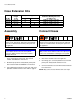
Assembly
1. Perform Pressure Relief Procedure for propor-
tioner and hydraulic power pack. See manual
313997 and 3A0238 for instructions.
2. Shutdown proportioner and hydraulic power pack.
See manual 313997 and 3A0238 for instructions.
3. Use supplied electrical tape to mark each end of the
hydraulic and material hoses. See table on page 3.
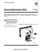
Connect Hoses
1. Disconnect hydraulic hoses from applicator.
2. Disconnect material hoses from applicator.
3. Use fittings (4) to connect hydraulic hoses from AC
power pack and hydraulic extension hoses.
4. Connect material hoses from HFR unit and material
hose extensions.
NOTE: Only connect hoses with the same color tape.
Kit No.
Length
ft (m)
Compatible Applicator
Maximum Working Pressure
psi (MPa, bar)
L-Head S-Head
24F235 25 (7.6)
✔
3500 psi (24 MPa, 241 bar)
24F236 50 (15.2)
✔
3500 psi (24 MPa, 241 bar)
24F237 25 (7.6)
✔
3500 psi (24 MPa, 241 bar)
24F238 50 (15.2)
✔
3500 psi (24 MPa, 241 bar)
Twisted hydraulic hoses can cause the hoses to
fatigue sooner and rupture. Ensure that the hydraulic
hoses do not twist between the AC power pack and
the applicator.
NOTICE
Ensure debris doesn’t enter into the hydraulic
hoses, the debris must be removed or machine
damage will result.
Twisted hydraulic hoses can cause the hoses to
fatigue sooner and rupture. Ensure that the hydraulic
hoses do not twist between the AC power pack and
the applicator.
NOTICE
Only connect hoses with the same color tape to pre-
vent cross contamination or damage to the system.