
User's Manual

Warnings
3A0471B 3
Installation
1. Locate unit where shock, vibration and ambient tem-
perature fluctuations are minimal. Do not mount in
ambient temperature areas exceeding 160°F
(71°C).
• Unit may be mounted in any position. However,
if installation location results in frequent expo-
sure to liquid it is recommended that the unit be
mounted vertically with the pressure connection
down.
• If the unit is to be set after mounting, raise
adjustment cover, then thread in pressure con-
nection until snug. Verify adjustment opening is
accessible.
2. Cut pressure switch cord to desired length.
3. Strip back insulation (see Table 1 for terminals and
corresponding color).
Table 1 - Terminal Colors
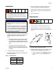
4. Mount using pressure connection: always use a
wrench on pressure connection wrench flats.
5. Attach conduit connection, hold electrical connec-
tion steady with wrench on hex, then thread in con-
duit.
6. Test unit before use.
Adjustments
1. Disconnect power to switch.
2. Connect switch to a calibrated pressure source.
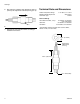
3. Slide adjustment cover (a) (open) toward cable. It
may be necessary to twist cover to overcome friction
(F
IG. 1).
4. Connect power to terminals or leads.
5. With the cable (b) facing up, insert the blade of a flat
screwdriver into the adjustment slot (c) (F
IG. 1).
• Turn the dial to the left to increase the setpoint.
• Turn the dial to the right to decrease the set-
point.
• A high or low limit switch is necessary for applica-
tion where a runaway condition could result.
• The adjustable range must be selected so that
incorrect, inadvertent setting at any range point
cannot result.
NOTICE
• Electrical ratings must not be exceeded. Over-
load on a switch can cause switch to fail on the
first cycle.
• Never exceed pressure limits. Unit can be oper-
ated up to maximum pressure on a limited basis
(i.e., set-up, testing) but continuous operation
must be restricted to the designated adjustable
range. Excessive cycling at maximum pressure
limits could reduce sensor life.
Terminals Color
N.O. Red
N.C. Black
Com White
FIG. 1
a
c
b