
User's Manual


Installation and Setup
8 3A0418E
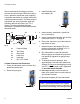
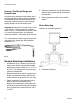
Graco recommends checking the counter
pressure by connecting an EM-Drive Lubrica-
tor to a pressure manometer (user supplied).
A pressure manometer is a simple device that
measures pressure output. To build a pressure
manometer you need a pressure gage (aa),
tee fitting (bb) and stop valve (cc). FIG. 2
shows a correctly assembled pressure
manometer, connected to the lubricator and a
lubrication point.
Counter Pressure Test Procedure
1. Clean the lubrication point to remove any
potential contaminants.
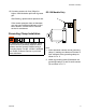
2. Remove the plug (A).
3. Install lubricator unit
into adapter (B).
4. Install reducers, extensions, grease line,
etc. (if necessary).
5. Screw a pressure manometer into the lubri-
cation point (dd) (FIG. 2, page 8).
6. Ensure the stop valve (cc) of the pressure
manometer is open.
7. Attach lubricator and adapter (B) to the
pressure manometer as shown in FIG. 2
and turn the switch to “ON” (ff).
8. Run manometer for about 20 seconds.
Observe gauge and repeat this procedure
until pressure registered on gauge stays
constant.
9. To determine counter pressure, wait
approximately 5 minutes until system has
relaxed. Do one
more discharge by turning
unit OFF; then ON again until it dispenses
for no more than 5 seconds.
10.Wait approximately 5 more minutes to
make sure system does not lose pressure
and remains constant.
11.Disconnect adapter (B) from manometer.
FIG. 2
aa
Pressure Gage
bb
Tee Fitting
cc
Stop Valve
dd
Lube Point
ee
Lubricator
ff
ON / OFF Switch
aa
bb
cc
dd
ee
ff
TI15375
A
NOTICE
Do NOT disconnect lubricator from adapter
(B). Screwing anything into end of lubricator a
second time will damage self-sealing threads.
B