
User's Manual


Installation and Setup
12 3A0417D
Circuit Board Settings
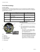
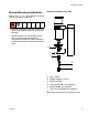
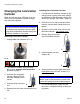
Function Display
Red and green LED’s (Light Emitting Diodes) are on the circuit board and visible through the
transparent cover. The following signals about operating conditions/malfunctions are displayed
by these LED’s for the user:
ALED Red
BLED Green
C 4-way code switch
D Plug connection
E Circuit board
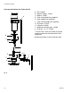
Setting Dip Switches
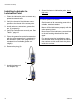
1. Unscrew and remove the cover of the drive
unit.
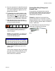
2. Use a small screwdriver or your finger to
move dip switches to the desired position.
Refer to Table 1.
• Dip switches 1 and 2 marked “TIME”
are used to set the discharge amount
per 100 operating hours.
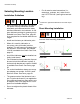
• Dip switches 3 and 4 marked “VOL” are
used to set the lubrication canister size.
If the 4-way code switch does not corre-
spond to the actual size of the lubrica-
tion canister, it will lead to a wrong
signal and over or under lubrication.
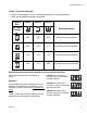
LED Signal Meaning
Green Steady System functions OK
Red Steady for less than 30 seconds with
motor running
Lubricator is discharging
Red Steady signal for more than 30 sec-
onds
Malfunction / error
Green and Red Steady signal Lubricator unit is empty.
Change canister.
FIG. 3
12 34
C
A
B
D
E