
User's Manual

Installation and Setup
10 3A0417D
Preparing Lubricator for
Installation
The lubricator has a self-protection mecha-
nism which shuts off the drive unit at counter
pressures higher than 5 bar (72.5 psi). Most
bearings require 0.5 - 2 bar (7.2 to 29 psi)
pressure (without tubes, extensions, angles,
etc.).
Use the following procedure to check the
counter pressure of the application prior to
installation.
NOTE:
• Be sure to use a lubricant cartridge that
contains the same grease used in the
application.
• The best measurement results are
achieved during operation.
Checking the Counter Pressure
1. Clean the lubrication point to remove any
potential contaminants.
2. Install reducers, extensions, grease line,
etc. (if necessary).
3. Prime the grease line and all accessories
with the same grease that is contained in
the lubricator. (See Parts, page 23 for a
complete list of available grease car-
tridges).
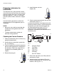
4. Remove the plug (A).
5. Install lubricator unit into
adapter (B).
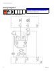
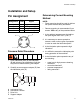
6. Screw a pressure manometer into the lubri-
cation point (dd) (FIG. 1).
A pressure manometer is a simple device that
measures pressure output. To build a pressure
manometer you need a pressure gage (aa),
tee fitting (bb) and stop valve (cc). FIG. 1
shows a correctly assembled pressure
manometer, connected to the lubricator and a
lubrication point.
7. Ensure the stop valve (cc) of the pressure
manometer is open.
8. Attach lubricator and adapter (B) to the
pressure manometer (aa - cc) and turn the
switch to “ON” (ff) (F
IG. 1).
A
FIG. 1
aa
Pressure Gauge
bb
Tee Fitting
cc
Stop Valve
dd
Lube Point
ee
Lubricator
ff
ON / OFF Switch
B
aa
bb
cc
dd
ee
ff