
User's Manual
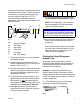
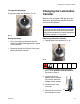

Installation and Setup
3A0416C 13
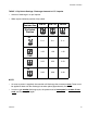
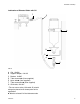
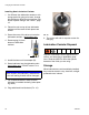
TABLE 1: Dip Switch Settings / Discharge Amounts in CC / Impulse
• Amount of discharge in cc per impulse.
• White square indicates position of dip switch.
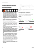
NOTE:
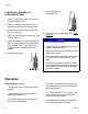
• As soon as power is supplied, the controller will discharge the set amount once. Power must
be applied at least until the discharge has taken place (approximately 2 minutes).
• In order to get another discharge cycle, the power must be interrupted for at least 15 sec-
onds, and then supplied again.
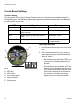
Lubrication
Canister Size
EM-60 EM-120 EM-250
Dip Switch
Position
2.11 2.11 2.11
1.06 1.06 1.06
0.53 0.53 0.53
0.26 0.26 0.26
34
VOL
34
VOL
34
VOL
12
ON
TIME
12
ON
TIME
12
ON
TIME
12
ON
TIME