
User's Manual

Setup
50 3A0294G
Setup
NOTE: For setup procedures specific your supply sys-
tem or pump assembly, refer to the Supply Systems
Operation manual or your specific pump package
instructions-parts manual.
Enter Password
If a password is enabled, the password entry screen
automatically opens when you change to setup mode.
Enter the password to access setup mode.
Setup Pump
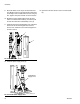
1. Follow the Installation guidelines on page 16.
2. Follow the Installation procedure for your particular
shot dispense kit. The procedures start on page 16.
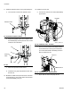
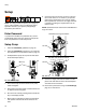
3. Fill displacement pump wet cup 2/3 full with Graco
Throat Seal Liquid (TSL
™
).
4. Attach electrically conductive fluid hose to pump
outlet and tighten.
5. Attach other end of electrically conductive fluid hose
to dispense valve and tighten.
6. Shut off the air valve by pressing the Air On/Off soft
key on the display module.
7. Back off the air regulators to their full counterclock-
wise position and close all shutoff valves for the
rams.
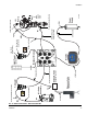
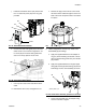
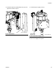
8. Connect the air line from the air source to the sys-
tem air inlet. See F
IG. 101. Refer to your specific
pump manual to determine the correct air supply
flow requirements. Connect an air supply hose that
is capable of meeting the required flow to the air
motor air inlet.
NOTE: Quick disconnects restrict flow for NXT2200 and
larger air motors.
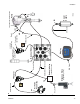
9. Connect air supply and electrical cable to the dis-
pense valve and solenoid valve. See the dispense
valve manual for instructions.
10. Flush and/or prime before using. See Prime/Purge,
page 52, for instructions.
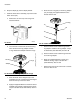
FIG. 100: Fill Wet Cup
Wet Cup
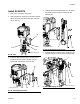
FIG. 101: Connect to Air Inlet
Air Inlet
Air Inlet
NXT1800 and Smaller Air Motors
NXT2200 and Larger Air Motors