
User's Manual

Installation
46 3A0294G
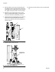
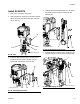
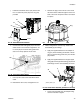
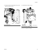
9. With integrated air controls only: Install valve
assembly (6) and fittings.
a. Apply the supplied adhesive to the pipe nipple
fitting (32). Screw the fitting into the air control
assembly.
b. Apply the supplied adhesive to the adapter fit-
ting (31) and the pipe swivel fitting (33). Screw
both fittings onto the valve assembly as shown.
c. Screw the entire assembly onto the pipe nipple
fitting. Use two wrenches to tighten.
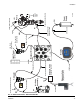
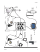
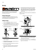
10. Install cables. Reference the cable identification
table below and F
IG. 93 for a diagram of cable con-
nections.
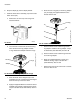
FIG. 91: Install Valve Assembly (with air controls)
r_262375_3A0294_35a
6
31
33
32
FIG. 92: Breakout Module Connections
Air Motor
Cable
LCM Cable
Solenoid
Extension
Cable
Light Tower
Shot Status
Drum Low (1)/
Start/Stop (2)
Not Used
Changeover
Solenoid
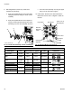
262375 Cable Identification
Description Part Labels (relative to graphic)
Length
in. (mm) Connectors
Power Cable
121226 PS1 None 16 (406.4)
DB25
15T859 1(blue) None 120 (3048)
Pigtail
15X619 AM1 LS1/RS1 17 (431.8)
Motor cable
9(grey) AM1 118 (2997.2)
Solenoid Extension
122030
3(red) Y1(yellow)
20 (508)
Accessory Kit
5(grey) Y2(orange)
Air Solenoid
121806
AV 1(yellow)
20 (508)
Fluid Solenoid
FV 2(yellow)
Pressure Sensor Exten-
sion
-- - - -