
User's Manual

Installation
3A0294G 45
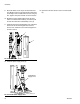
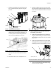
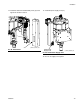
j. Install the reed switch sensor (23). Secure with
the 1 in. (255 mm) screw (25) and o-ring (24)
provided.
k. Connect the strain relief guide (27) to the reed
switch sensor. Use a wrench to tighten the 1/2
in. screw (26) on the strain relief guide and to
secure it to the top plate of the air motor.
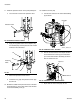
l. Use a zip tie to secure the reed switch sensor
cable.
m. Reinstall the valve cover, and tighten the nut.
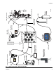
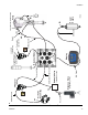
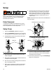
n. Remove the plug in the air motor cover. Route
the linear sensor cables through the hole in the
back of the cover. Snap the air motor cover back
into place.
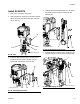
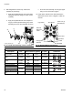
8. Without integrated air controls only: Install valve
subassembly (6) and fittings.
a. Apply the supplied adhesive to the adapter fit-
ting (31). Screw the fitting into bottom of the air
valve so that the fitting points away from the dis-
play module.
b. Apply the supplied adhesive to the pipe nipple
fitting (32) and the pipe swivel fitting (33). Screw
both fittings onto the valve assembly as shown.
c. Screw entire assembly onto the adapter fitting.
Use two wrenches to tighten.
FIG. 87: Install Reed Switch Sensor
FIG. 88: Install Strain Relief Guide
Screw
Cover
25
24
23
26
27
FIG. 89: Remove Plug
FIG. 90: Install Valve Assembly (without air controls)
Plug
33
6
31
32
r_262375_3A0294_34a