
User's Manual

Installation
44 3A0294G
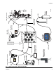
6. Snap the display (5) into the display bracket.
7. Install the linear sensor assembly (18) and the reed
switch sensor (22).
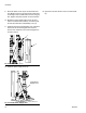
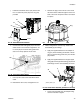
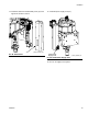
a. Remove the air motor top cover using a flat
head screwdriver.
b. Use a wrench to remove the air motor lift ring.
Then remove the lift ring adapter and both
o-rings. Discard the adapter and both o-rings.
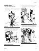
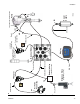
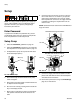
c. Place the linear sensor magnet (13) on the
installation tool (27), and then insert the magnet
down into the top of the motor shaft.
d. Apply the supplied adhesive to the linear sensor
assembly (18) threads. Install the linear sensor;
torque to 30-36 ft-lbs (40.6-48.8 N•m). See F
IG.
86.
e. Place the new o-ring (20) on the lift ring adapter
(19), and apply the supplied adhesive to the
threads. See F
IG. 86.
f. Route the linear sensor cable through the lift
ring adapter. Install the lift ring adapter; torque
to 30-36 ft-lbs (40.6-48.8 N•m). See F
IG. 86
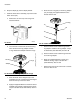
g. Route the linear sensor cable through the hole
on the lift ring adapter.
h. Apply the supplied adhesive to the lift ring.
Install the lift ring; torque to 30-36 ft-lbs
(40.6-48.8 N•m). See F
IG. 86.
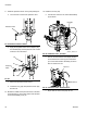
i. Remove the screw on the valve cover to remove
the cover. See F
IG. 87.
FIG. 84: Remove Air Motor Cover
FIG. 85: Remove Lift Ring Adapter and O-rings
ti8218b
r_262373_3A0294_before _linear
O-rings
Adapter
Lift Ring
FIG. 86: Install Linear Sensor
13
18
19
Lift Ring
20
r_262373_3A0294_after_linear