
User's Manual

Installation
3A0294G 39
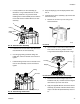
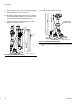
NOTE: For air motor models M07xxx, M12xxx, and
M18xxx, which have the large mufflers, remove the muf-
fler before installing the reed switch. Reinstall the muf-
fler after the reed switch is installed.
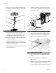
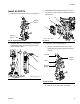
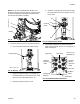
7. Install the pressure sensor on the pump bleed port.
a. Use a wrench to remove the pressure valve.
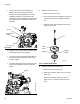
b. Apply the supplied sealant to the adapter (27),
the manifold (28), and the pressure valve. Install
all three in the order listed. See F
IG. 75.
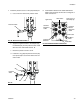
c. Disconnect pressure sensor at PT1.
d. Install the o-ring (33) and pressure sensor (29);
use zip ties (26) to secure the cable to the ram
and air hose.
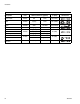
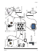
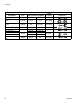
8. Install cables. Reference the cable identification
table on the next page and F
IG. 77 for a diagram of
cable connections.
FIG. 73: Install Reed Switch
FIG. 74: Remove Pressure Valve
r_262374_3A0294_71a
Muffler
19
20
Pressure Valve
r_262370_3A0294_19a
FIG. 75: Install Pressure Sensor
FIG. 76: Breakout Module Connections
Pressure
Valve
r_262370_3A0294_20a
27
29
28
33
Pressure
Sensor
Extension
Air Motor
Cable
Cable
LCM Cable
Solenoid
Extension
Cable
Light Tower
Shot Status
Drum Low (1)/
Start/Stop (2)
Not Used
Changeover
Solenoid