
User's Manual
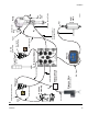

Installation
3A0294G 31
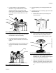
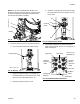
c. Loosely install the air valve assembly (3).
Grease the o-ring included with the air valve
assembly. Install the o-ring and then finish
installing the air valve assembly. Secure with the
two screws that are included with the air valve
assembly.
d. Install the new air motor slider valve label that is
included with the air valve assembly.
e. Coat the gauge fitting and elbow fitting with
PTFE tape, and then reinstall. Use a wrench to
tighten.
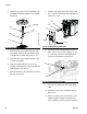
f. Install the fitting and air hose on the back of the
new air valve assembly. Use two wrenches to
tighten.
5. Snap the display (5) into the display bracket. See
F
IG. 51.
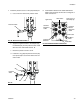
6. Install the linear sensor assembly (18) and the reed
switch sensor (22).
a. Remove the air motor top cover using a flat
head screwdriver.
b. Use a wrench to remove the air motor lift ring.
Then remove the lift ring adapter and both
o-rings. Discard the adapter and both o-rings.
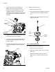
c. Place the linear sensor magnet (13) on the
installation tool (27), and then insert the magnet
down into the top of the motor shaft.
d. Apply the supplied adhesive to the linear sensor
assembly (18) threads. Install the linear sensor;
torque to 30-36 ft-lbs (40.6-48.8 N•m). See F
IG.
57.
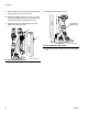
FIG. 53: Install Air Valve Assembly
FIG. 54: Install Fitting and Air Hose
Screw
Slider Valve
O-ring
3
r_262373_3A0294_31a
Label
Fitting
Air Hose
r_262373_3A0294_32a
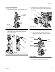
FIG. 55: Remove Air Motor Cover
FIG. 56: Remove Lift Ring Adapter and O-rings
ti8218b
r_262373_3A0294_before _linear
O-rings
Adapter
Lift Ring