
User's Manual


Installation
3A0294G 25
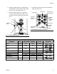
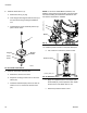
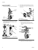
5. Loosen two screws on the top air controls bracket.
Install the display module bracket (2) using two
screws (24) and lock washers (23) to secure it to the
air controls bracket.
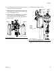
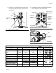
6. Install the air valve subassembly (3).
a. Use two wrenches to remove the air hose,
elbow fitting, and pressure gauge from the air
controls.
b. Remove the air motor slider valve label. See
F
IG. 15.
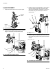
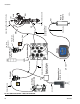
c. Loosely install the air valve assembly (3).
Grease the o-ring included with the air valve
assembly. Install the o-ring and then finish
installing the air valve assembly. Secure with
screw.
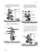
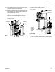
d. Install the new air motor slider valve label that is
included with the air valve assembly. See F
IG.
37.
e. Coat the gauge fitting with PTFE tape, and then
reinstall. Use a wrench to tighten. See F
IG. 37.
f. Coat the elbow fitting with PTFE tape. Reinstall
the fitting and air hose on the back of the new
air valve assembly. Use two wrenches to
tighten.
7. Snap the display (5) into the display bracket.
FIG. 36: Install Display Module Bracket
FIG. 37: Air Control Assembly
2
24
23
r_262371_3A0294_31a
Air Hose
Label
Elbow
Fitting
Pressure
Gauge
FIG. 38: Install Air Valve Assembly
FIG. 39: Install Elbow Fitting
3
O-ring
Screw
r_262370_3A0294_11a
Slider Valve
Label
Elbow
Fitting
r_262370_3A0294_34a