
User's Manual


Installation
3A0294G 21
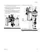
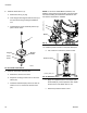
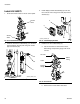
b. Apply the supplied sealant to the adapter (36),
the manifold (37), and the pressure valve. Install
all three in the order listed. See F
IG. 27.
c. Disconnect sensor cable at PT1. Install the
o-ring (41) and pressure sensor (38); use zip
ties (35) to secure the cable to the ram and air
hose.
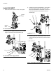
9. Install cables. Reference F
IG. 29 for a diagram of
cable connections and
FIG. 27: Install Pressure Sensor
37
Pressure
Valve
r_262370_3A0294_20a
36
38
41
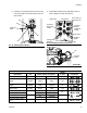
FIG. 28: Breakout Module Connections
Pressure
Sensor
Extension
Air Motor
Cable
Cable
LCM Cable
Solenoid
Extension
Cable
Light Tower
Shot Status
Drum Low (1)/
Start/Stop (2)
Not Used
Changeover
Solenoid
262370 and 262372 Cable Identification
Description Part labels (relative to graphic)
Length
in. (mm) Connectors
Power
121226 PS1 None 16 (406.4)
DB25
15T859 1(blue) None 120 (3048)
Pigtail
15X619 AM1 LS1/RS1 17 (431.8)
Motor
15Y051 9(grey) AM1 118 (2997.2)
Solenoid Extension
122030
3(red) Y1(yellow) 20 (508)
Accessory Kit
5(grey) Y2(orange) 20 (508)
Air Solenoid
121806
AV 1(yellow) 20 (508)
Fluid Solenoid
FV 2(yellow) 20 (508)
Pressure Sensor Extension
16F562 6(blue) PT1 80 (2032)