
User's Manual

Installation
20 3A0294G
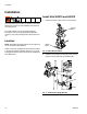
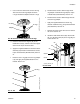
l. Connect the strain relief guide (26) to the reed
switch sensor. Use a wrench to tighten the
1/4-20 x 1/2 in. screw (25) on the strain relief
guide and to secure it to the top plate of the air
motor.
m. Use a zip tie to secure the reed switch sensor
cable.
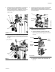
n. Reinstall the valve cover, and tighten the nut.
See F
IG. 22.
o. Remove the plug in the air motor cover. Route
the linear sensor cables through the hole in the
back of the cover. Snap the air motor cover back
into place.
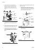
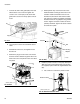
p. D200 systems only: reconnect the air motor.
Install threaded rod through center hole in the
crossbar. Install lock washers and nuts onto
threaded rod, both above and below crossbar.
Use wrench to hold lift ring adapter and tighten
threaded rod into lift ring adapter using another
wrench. Tighten nut below crossbar to 25 ft-lb
(34 N•m) maximum. Tighten nut above crossbar
to lock motor in place.
8. Install the pressure sensor on the pump bleed port.
D60 rams only: If pump bleed valve is longer than
the supplied, replace it with the supplied bleed valve
(65).
a. Use a wrench to remove the pressure valve.
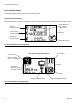
FIG. 23: Install Strain Relief Guide
FIG. 24: Reinstall Air Motor Cover
25
26
Plug
r_262370_3A0294_17a
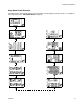
FIG. 25: Reconnect Air Motor
FIG. 26: Remove Pressure Valve
Rod
Nut
Nut
Washer
Lift Ring
Adapter
ti11169a
Pressure Valve
r_262370_3A0294_19a