
User's Manual

Installation
3A0294G 17
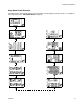
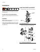
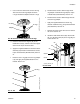
3. Install the electronics subassembly (1) to the side of
the power supply bracket using four screws (34).
Also secure the bracket to the bottom of the air con-
trol bracket using two screws (29) and two lock
washers (28).
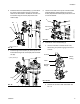
4. Install the light tower bracket (31) to the top air con-
trols bracket using three screws (29) and lock wash-
ers (28).
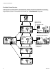
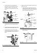
5. Loosen two screws on the top air controls bracket.
Install the display module bracket (2) using two
screws (29) and lock washers (28) to secure it to the
air controls bracket.
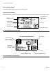
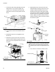
6. Install the air valve subassembly (3).
a. Use two wrenches to remove the air hose,
elbow fitting, and pressure gauge from the air
controls.
b. Remove the air motor slider valve label. See
F
IG. 15.
FIG. 12: Install Electronics Assembly
FIG. 13: Install Light Tower Bracket
1
34
29
28
r_262370_3A0294_7a
31
28
29
r_262370_3A0294_8a
FIG. 14: Install Display Module Bracket
FIG. 15: Air Control Assembly
2
29
28
r_262370_3A0294_9a
Air Hose
Label
Elbow
Fitting
Pressure
Gauge