
User's Manual


Appendix B - I/O
3A0260H 97
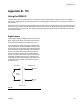
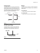
Analog Inputs
The PGM receives a flow rate analog command from
the automation. The 0 to 10 VDC analog input is refer-
enced to analog common on the control. See F
IG. 42.
The reference for the automation controller analog out-
put must be connected to the PGM analog reference
(pin 8) for this signal to function properly.
24 VDC From E-Stop
The PGM provides a signal that can be used by the
automation controller to monitor the emergency stop
switch position of the PGM controller. See F
IG. 43.
Relays
If the use of relays is required to condition the digital I/O
signals, these are some examples of part numbers that
could be used.
For 24 VDC Coils:
• Relay: Phoenix Contact Part Number: 2966171
For 120 VAC Coils:
• Relay: Phoenix Contact Part Number: 2966197
F
IG. 42
F
IG. 43
AutomationPGM Control
Analog Input
0 to 10 VDC
Voltage
Pin 8
Pin 7
+
-
_
+24 VDC
E-Stop Switch
Pin 14