
User's Manual


Repair
44 3A0260H
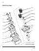
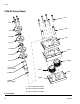
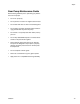
PGM-6 Pump Assembly
1. Place the back plate (1603) on a table inside facing
up.
2. Place the driven gear (1608) on its stud (1606).
3. Place gear case (1602) onto back plate (1603).
Check orientation of dowel pin holes to assure they
align with the ones in the back plate.
4. Slide drive gear (1607) onto drive shaft (1605). Ver-
ify shaft key (1609) is installed properly.
5. Install drive gear (1607) and drive shaft (1605) into
back plate (1603).
6. Position top plate (1601) over drive shaft (1605) and
place onto gear case (1602).
7. Rotate the gears several times to ensure free rota-
tion.
8. Insert the dowel pins (1610) and rotate the gears
several times to ensure free rotation.
NOTE: Dowel pins are not a press fit and may be
installed using a plastic hammer if necessary.
9. Install pump plate screws (1613) and tighten to
85-105 in-lb (9.6-11.8 N•m).
10. Rotate the gears several times to ensure free rota-
tion.
11. Apply a heat resistant, non-evaporating lubricant to
the seal area of the drive shaft (1605).
12. Install new seals (1612). See F
IG. 26 and FIG. 27.
13. Install seal retainers (1611) and seal retainer screws
(1614). Tighten screws to 85-105 in-lb
(9.6-11.8 N•m).
14. Align pump shaft key and slide coupling onto pump
shaft. Tighten coupling bolt just enough to hold it’s
position.
15. Attach servo motor, gear head, and top plate to
pump assembly. See F
IG. 20.
16. Separate coupling until proper gap is created. See
F
IG. 21.
17. Tighten pump block mounting shoulder bolts to
frame (1102).
18. Replace all electrical connections and fluid connec-
tions before applying fluid pressure and power.
NOTICE
Do not hammer or force components together or
damage may occur. Parts will drop into place if
properly cleaned and aligned. Use of a compatible
oil is recommended during assembly.
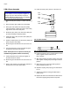
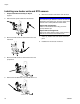
FIG. 26: Seal Locations
FIG. 27: Seal Orientation
1515,
1614
1512,
1611
*1513,
1612
Pump Body