
User's Manual


Repair
3A0260H 43
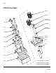
PGM-6 Pump Disassembly
1. Prepare Gear Meter Assembly for Repair,
page 37.
2. Refer to Gear Pump Maintenance Guide on
page 49 for special notes regarding gear pump
repair.
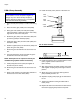
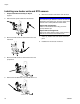
3. Remove four pump block shoulder bolts (1102).
4. Remove drive assembly. See F
IG. 23.
5. Remove seal retainer fasteners (1614) and seal
retainers (1611).
6. Remove pump dowel pins (1610) using an arbor
press.
7. Remove the pump plate screws (1613).
8. Separate the pump front plate (1601), gear case
(1602) and back plate (1603).
NOTE: Notches on the pump plates can be used to
separate the plates.
9. To remove the drive shaft (1605) from the bottom
plate (1603) press the shaft and gear from the bot-
tom pump plate towards the coupling end.
10. To remove the drive gear (1607) from the drive shaft
(1605) Support the drive gear at the lower end to
allow the shaft to be pressed through the gear from
the top or coupling end. Make sure to leave clear-
ance for the drive key.
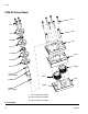
11. The stud (1606) for the driven gear (1608) is press
fit into the back plate (1603) and need not be
removed if not worn.
12. Clean all components thoroughly before reassem-
bly. The use of an ultrasonic cleaner is recom-
mended.
NOTICE
Pump section should be fully supported to prevent
damage being dropped. It is recommended that the
gear meter assembly be located on a work bench
for service.
NOTICE
Thicker materials may pump heating prior to disas-
sembly. Do not expose the pump to thermal shock.
Raise temperature at a maximum rate of 180°F
(100°C) per hour. Do not exceed 400°F (204°C).
Gradually cool the pump to room temperature.
NOTICE
Do not use a hammer to remove dowel pins as this
will damage the pump.
NOTICE
The PGM pump design relies on a lap fit between
components for performance and sealing. Be care-
ful not to drop the gears (1607, 1608) or damage
the mating surfaces of the pump plates (1601,
1603) and gear case (1602). To prevent damage, do
not use pliers or screwdrivers to remove the gears.