
User's Manual


Repair
3A0260H 41
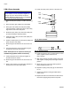
3. Remove drive assembly. See FIG. 23.
4. Perform Remove Dispense Valve procedure.
5. Loosen 4 bolts (407) and remove front block (412).
6. Loosen 4 bolts and remove inlet block (110, 1302).
7. Loosen pump bolts (3, 1303) and remove
pump (108, 1309).
8. Replace front block o-ring (105, 1305).
9. Install front block (412) onto pump block (109,
1308).
10. Replace inlet block o-ring (107, 1306).
11. Install inlet block (102, 1302) onto pump block.
12. Replace pump block o-rings (106, 104; 1304). See
F
IG. 24.
13. Place pump (109, 1308) onto pump block. Install
bolts (103, 1303) hand tight.
14. Locate drive assembly on top of pump assembly.
15. Tighten pump block mounting shoulder bolts to
frame (4, 1102).
16. Loosen pump bolts (103, 1303) as needed to
ensure couplings are aligned.
17. Tighten pump bolts to 430 in-lb (48.58 N•m).
18. Replace all electrical connections and fluid connec-
tions before applying fluid pressure and power.
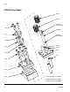
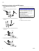
FIG. 23
4, 1102
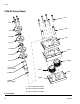
FIG. 24
*107, 1306
105,
1305*
102, 1302
104, 1304
* Provided in o-ring kit 24E626.
103,
1303
106,
1304
109,
1308
412
407
108,
1309