
User's Manual


Models
4 3A0260H
Models
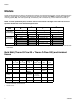
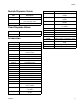
Check the identification (ID) plate for the 6-digit part number of the fluid metering system. Use the following matrix to
define the construction of the system, based on the six digits. For example, Part PG0111 represents a PGM fluid
metering system (PG), with a 6cc system (0), unheated (1), with controls/3m (1), and an Endure snuff-back (1).
NOTE: To order replacement parts, see Parts section in this manual. The digits in the matrix do not corre-
spond to the Ref. Nos. in the Parts drawings and lists.
* PGM Control Center does not include heat controls. Heat loads are configured to be controlled by Therm-O-Flow
Controllers.
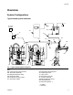
Bulk Melt (Therm-O-Flow 20 + Therm-O-Flow 200) and Ambient
Hoses
* Indicates PTFE hose, all others Buna-N.
† Indicates swivel.
PG 0
1
1
2
First and
Second Digits
Third Digit
Fourth Digit
Fifth Digit
Sixth Digit
Size
Heat
Controls *
Valve
Description Description Description Description
PG
(Precision
Gear Meter)
0 6cc 1 Unheated 0 No controls 1 Endure snuff-back
2 20cc 2 Heated 1 Controls / 3m 6 Remote mount
2 Controls / 6m
3 Controls / 9m
4 Controls / 15m
Hose Diameter
- 8
3/4 in. - 16 JIC
- 10
7/8 in. - 14 JIC
- 12
1-1/16 in. - 12
JIC
- 16
1-5/16 in. - 12 JIC 3/8 in. 1/2 in.
Hose Length
6 ft None 115875 None 115884 109163 626720
(1/2 in. x 5 ft)
10 ft 115873 115876 115880 115885 None 215441
15 ft Non None None None 109165/
685602*
511381*
Fittings
PGM Inlet
(-16 SAE)
None None 124238
124235 (90°)
124239
124243 †
124236 (90°)
None None
PGM Outlet
(3/4 in. npt)
124286 C20595 15M863 107127 124290 † 124289 †
Valve Inlet 124287 C20768 107052 124288 158256 † 190451 †