
User's Manual

Repair
38 3A0260H
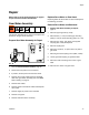
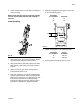
Install Servo Motor or Gearhead
1. Remove key from motor shaft.
2. Slide the gear head bushing into the drive coupling
and align slots in drive coupling and bushing. See
F
IG. 19.
3. Rotate the drive coupling to align clamping bolts
with access holes.
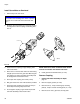
4. Place motor on work surface with motor shaft facing
straight up then mount the gear head. Mounting the
gear head in any other orientation will usually lead
to misalignment and excessive noise.
5. Pre-torque drive coupling to 0.4 N•m (4 in-lb).
6. Bolt gear head to the motor with fasteners provided.
7. Final toque drive coupling to 8.5 N•m (76 in-lb) in
three steps increasing torque each time.
8. Do not tighten coupling to gear head output shaft
until drive assembly is mounted in frame.
NOTE: Orient servo motor so that the motor connec-
tions do not interfere with material inlet hose.
9. Install gussets with shoulder bolts (5, 1104).
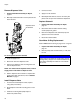
Remove Coupling
1. Prepare Gear Meter Assembly for Repair,
page 37.
2. Remove support gussets (9, 1106).
3. Remove bolts (1, 1103) connecting top mounting
plate (8, 1105) to vertical mounting plate (10, 1107).
4. Remove servo motor, gear head, and top plate.
NOTICE
Use caution when handling servo motor to prevent
damage. Do not use tools that could cause dam-
age.
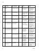
FIG. 19
SEE DETAIL
A
DETAIL
A
SCALE
3/2