
User's Manual

Repair
3A0260H 37
Repair
NOTE: Refer to Parts section beginning on page 51
for part reference number identification.
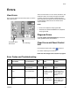
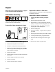
Gear Meter Assembly
This section describes how to remove and replace com-
ponents on the gear meter assembly.
Prepare Gear Meter Assembly for Repair
1. Perform Pressure Relief Procedure, page 28.
2. Disconnect main power at the control box.
3. If present, remove power from the heat control.
4. Remove servo power cable and servo feed back
cable. See gear meter assembly parts; see Parts
section starting on page 51.
5. Remove heat cables.
6. Remove pressure transducer cables and dispense
valve cable.
7. Remove supply air pressure from solenoid.
8. Remove front guard.
9. Remove material hoses if necessary.
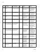
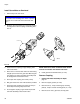
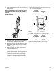
Replace Servo Motor or Gear Head
Replacing either the Servo Motor or Gear Head requires
the following procedure.
Remove Servo Motor and Gearhead
1. Prepare Gear Meter Assembly for Repair,
page 37.
2. Remove support gussets (9, 1106).
3. Remove bolts (1, 1103) connecting top mounting
plate (8, 1105) to vertical mounting plate (10, 1107).
4. Remove servo motor, gear head, and top plate.
Coupling (303, 1203) will separate.
5. Remove coupling half
6. Remove 4 screws (3, 1110) that mount to plate to
gear head.
7. Remove gear head coupling covers (302a, 1202a).
8. Loosen gearhead coupling on gearhead shaft.
9. Remove 4 bolts connecting servo motor to gear-
head.
10. Remove servo motor from gear head.
FIG. 18