
User's Manual


Installation
3A0260H 17
Grounding
Ground the gear meter assembly as instructed here and
in the individual component manuals. Make sure the
gear meter assembly and its components are installed
correctly to ensure proper grounding.
Air and Fluid Hoses
For static dissipation, use only electrically conductive
hoses or ground the applicator / dispense valves.
Dispense Valve
Follow the grounding instructions in the dispense valve
manual.
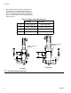
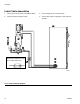
Connect Fluid and Air Lines
Follow the instructions in your separate component
manuals to connect air and fluid lines. The following are
only general guidelines.
• The PGM gear meter assembly should be installed
on the automation unit or in another appropriate
place, as close as practical to the dispense valve.
• For a remote mount dispense valve, connect a
fluid line between the gear meter outlet and the dis-
pense valve. Shorter fluid lines (hoses) will provide
better fluid system response.
• See page 4 for list of inlet fittings.
• Air must be clean and dry, between 60-100 psi
(0.41-0.68 MPa, 4.14-6.89 bar). Flush air line before
plumbing in air filter assembly (234967). Plumb in air
filter assembly near air drop site (upstream of PGM).
Adding an air regulator to this line will provide more
consistent dispense valve response times.
• Connect a 1/4 in. OD air supply line to the inlet port
on the PGM air supply inlet.
NOTE: To maximize system performance keep the
dispense hose length as short as the application
will allow.
NOTICE
If power and grounding connections are not done
properly, the equipment will be damaged and the
warranty voided.
NOTICE
Route all fluid and air lines carefully. Avoid pinching
and premature wear due to excessive flexing or rub-
bing. Hose life is directly related to how well they are
supported.
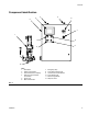
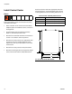
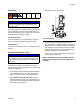
FIG. 8: Inlet Fitting