
User's Manual


Parts
46 3A0238P
1.68
+.00
-.01
.07
+.00
-.01
208
251
250
210
207
263
209
7
12
20
19
10
13
1
1
202
212
211
201
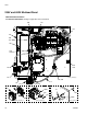
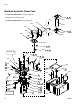
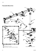
Assemble coupler (202, 212) to specified dimension prior to
mounting motor and pump to housing.
Torque to 40 ft-lbs (54 N•m).
Torque to 35 ft-lbs (47 N•m).
Torque to 70 ft-lbs (95 N•m).
Torque to 15 ft-lbs (20 N•m).
Torque to 185 in.-lbs (20 N•m).
Torque to 62 in.-lbs (7 N•m).
Torque to 65 in.-lbs (7.3 N•m).
Torque to 10 ft-lbs (13 N•m).
Torque to 40 in.-lbs (4.6 N•m).
Torque 1/4 turn past hand tight.
Apply PTFE tape on installation end only prior to assembly.
Apply sealant to threads prior to assembly.
Apply a light coating of lubricant to seals prior to assembly.
Tighten tubing nuts hand tight and then with a wrench. Torque
1-1/2 flats.
Directional valves are supplied with o-rings.
Route all signal cables through cable ties on the filter side of the
power pack.
Route all power wires through cable ties on the filler side of the
power pack.
Apply lubricant to contact side of thermal switch harness (250)
prior to assembly.
Install roll pin (263) into diverter block (207) for orientation to
hydraulic housing (206).
Cables and leads removed for clarity.
1
2
3
4
5
6
7
8
9
10
11
12
13
14
15
16
17
18
19
20
21