
User's Manual


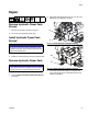


Repair
3A0238P 29
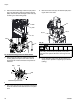
Install Hydraulic Power Pack
1. Run a rope through the three eye-bolts and between
the motor and the accumulator. Secure to a hydrau-
lic lift. See FIG. 24 on page 28.
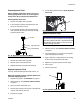
2. Lift the Hydraulic Power Pack and place onto the
base enclosure. See FIG. 25.
3. Align the holes with the tank then install finger-tight
the four bolts (57) and washers (56) securing the
tank to the stand. Torque to 10 ft-lb (13.5 N•m).
4. Remove rope and lift.
5. Remove eye-bolts. Install original bolts (258) into
fluid housing (206). See FIG. 24 on page 28.
6. Connect all electrical cables to the motor, three
directional valves, temperature switch, and pressure
transducer.
7. Connect all hydraulic lines to applicator housing.
See FIG. 21 on page 27.
8. Connect heat exchanger inlet hose (76) and fitting
to elbow fitting (249) on hydraulic housing (206).
Connect heat exchanger outlet hose (77) and fitting
to elbow fitting (248). See FIG. 23 on page 28.
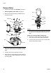
Replace Tank Gasket
1. Remove Hydraulic Power Pack. See page 27.
2. Remove hex head cap screws (239) and washers
(238) securing hydraulic housing (206) to tank
(237). Carefully remove motor (201) and hydraulic
housing assembly from tank.
3. Remove tank gasket (236). If tank (237) is dam-
aged, replace tank.
4. Install thrust washers (038) onto hex head cap
screws (039). Apply pipe sealant 070408 to threads
of screws. Align tank gasket (036), hydraulic hous-
ing, and tank (020) then install screws. Torque to
15 ft-lb (20.3 N•m).
5. Perform Install Hydraulic Power Pack procedure,
see page 29.
NOTICE
If any debris falls into the hydraulic tank, the debris
must be removed or machine damage will result.
NOTICE
Do not over-torque any item that threads into the
hydraulic tank. This will strip the threads and require
tank replacement.
NOTICE
Do not over-torque any item that threads into the
hydraulic tank (237). This will strip the threads and
require tank replacement.
FIG.26
239
238
206
236
237