
User's Manual


Setup
3A0238P 19
Connect Communication Cables
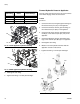
1. Feed end of communication cable (83) through bulk-
head of the HFR base unit.
2. Connect communication cable (83) to any open
CAN connector of a GCA cube.
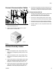
Connect Proximity Cables
L-Head
1. Connect the applicator end of the proximity sensor
cable (418) to the dispense proximity sensor on the
L-Head.
2. Connect the applicator end of the proximity sensor
cable (419) to the cleanout proximity sensor on the
L-Head.
3. Connect the other end of the proximity sensor cable
(418) to the dispense proximity sensor cable (122),
labeled A1, on the AC power pack. See FIG. 13.
4. Connect the other end of the proximity sensor cable
(419) to the cleanout proximity sensor pigtail (123),
labeled 2C, on the AC power pack. See FIG. 13.
5. Connect the ter mination connector (425) to the con-
nector (121), labeled 5A. Feed the connector (425)
and cables (121, 84) into the base cube and secure.
S-Head (Includes GX-16)
1. Connect control cable (84) to the motor control mod-
ule splitter labeled “2A” found on the HFR unit.
Refer to the HFR manual for detailed locations
2. Connect the S-head proximity sensor to the electri-
cal connector found within the material hose bundle.
3. Connect the other end of the cord to the electrical
connector found near the fluid manifold on the HFR.
4. Feed the cables (121, 122, 123) into the base cube
and secure.
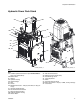
FIG.13
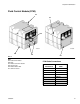
FIG.14
83
121
122
123
84
TI12337A