
User's Manual


Setup
3A0238P 15
Setup
1. Anchor the stand to the floor (mounting hardware
not included). See Dimensions on starting on page
66 for mounting dimensions. Suggested anchors:
McMaster-Carr (part no. 92403A400).
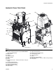
NOTE: The AC power pack (A) needs to be mounted
no more than 6 ft (1.8m) away from the front of the
GMS unit.
2. If the AC power pack has a boom (C), anchor the
boom to the floor (mounting hardware not included).
See Dimensions on starting on page 66 for mount-
ing dimensions. Suggested anchors: McMaster-Carr
(part no. 92403A400).
NOTE:
• If your AC Power Pack Module has a boom (C),
the AC Power Pack (A) needs to be installed
within 12 in. (304.8 mm) of the boom and the
boom needs to be installed within 3 ft (1 m) of
the GMS unit.
• Ensure that the hose connections for applicator
(D) face the mast. See FIG.1onpage10.
3. If the AC power pack has a boom (C), mount the
applicator (D) to the boom (C). Complete Installa-
tion instructions in the applicator manual.
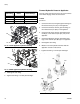
Connect Hydraulic Hoses
Connect Hydraulic Hoses to Power Pack
1. Connect L-Head hydraulic hoses:
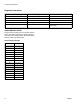
a. Connect the hydraulic hose fittings (A1, A2, B1,
and B2) on the AC power pack to the ends of
hydraulic hose (401) on the mast side of the
boom (C) as listed in the table below. See FIG.
1, page 10 and FIG. 6, page 16.
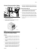
2. Connect S-Head and GX-16 hydraulic hoses:
a. Connect the hydraulic hose fittings (A2 and B2)
on the AC power pack to the ends of hydraulic
hose (402) on the mast side of the boom (C) as
listed in the table below. See FIG. 1, page 10
and FIG. 6, page 16.
b. Use caps (6) to plug A1 and B1 fittings.
Avoid breathing of vapors and contact with Isocyante
as some people have severe allergic reactions. See
Isocyanate Conditions on page 8.
Avoid routing hoses in walkway areas to prevent
operators from tripping on hoses running between
system components.
Hydraulic lines could rupture and cause injury. Use
hydraulic hoses with a pressure rating higher than
what the system is set to.
Twisted hydraulic hoses can cause the hoses to
fatigue sooner and rupture. Ensure that the hydraulic
hoses do not twist between the AC power pack and
the applicator.
NOTICE
Damage can occur to the directional valve if the
hydraulic hose diameter is larger than 3/8 in. (9.5
mm).
To prevent damage to the applicator or directional
valves, do not allow any dirt or foreign matter to
enter the lines, when connecting the hose kit (B) to
the applicator (D) and hydraulic power pack (A).