
User's Manual


Installation
Encoder Encoder
Encoder
Installation Installation
Installation
(PC (PC
(PC
- -
-
8e 8e
8e
only) only)
only)
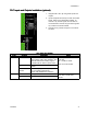
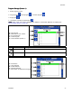
1.Connectuptotwoencoderstomonitorline
speed.NOTE: NOTE:
NOTE:
TheseareusedforLine1orLine
2onthescreen.
NOTE: NOTE:
NOTE:
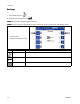
Encodertypemustbequadrature
differentiallinedriver(RS422).Scalingisentered
intheencodersetupscreenusingthelive
calibrationfeature.
NOTE: NOTE:
NOTE:
SomeencodershaveZandZ’
connections.Thesearenotusedanddonot
needtobeconnected.
NOTE: NOTE:
NOTE:
Encoderdirectioncanbereversedby
swappingAandA’withBandB’.Dothislineif
linespeedreadsnegativeonthedisplay.
Graco Graco
Graco
Encoder Encoder
Encoder
Wiring Wiring
Wiring
Diagram Diagram
Diagram
Terminal Terminal
Terminal
Function Function
Function
Wire Wire
Wire
Color Color
Color
Plus(+)15VSupply
Red
APhaseAsignal
(RS422)
Brown
A’PhaseAsignal
return
White
BPhaseBsignal
(RS422)
Yellow
B’PhaseBsignal
return
Green
Minus(-)
ReturnBlue
PE
Shield
Bare
Run Run
Run
Up Up
Up
Installation Installation
Installation
(PC (PC
(PC
- -
-
8e 8e
8e
only) only)
only)
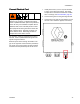
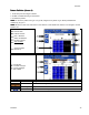
1.Connectuptotwo“I/P”or“V/P”run-upair
pressureregulatorstovarypumppressurebased
onlinespeed.Hardwareautomaticallydetects
whetheranI2PorV2Pisconnected.
NOTE: NOTE:
NOTE:
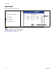
Pressurevs.linespeedsettingsare
enteredontherun-upsetupscreen(seeRunUp
Control(Screens6–7,PC–8eonly),page26).
Standard Standard
Standard
Wire Wire
Wire
Colors Colors
Colors
Terminal Terminal
Terminal
Function Function
Function
M12 M12
M12
Cable Cable
Cable
Plus(+)24VSupply
Brown
%Outputtorun-up
Black
Minus(-)
ReturnBlue
Minus(-)
ReturnWhite
12
334784A