
User's Manual


Installation
334495B 3
Installation
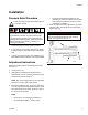
Pressure Relief Procedure
Follow the Pressure Relief Procedure whenever
you see this symbol.
1. Disconnect power to the lubrication controller.
2. If connected to an air supply, disconnect air supply
to pump module to ensure the system is depressur-
ized.
3. Consult your pump manual for any additional pres-
sure relief instructions related to your pump module.
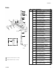
Adjustment Instructions
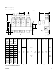
Reference numbers used in the following instructions
refer to F
IG. 1.
1. Loosen lock nut (7).
2. Hand tighten the Adjuster Nut (8) then loosen,
approximately 1/2 turn to achieve the minimum dis-
pensed output volume (0.001 in.
3
).
NOTE: Any output setting below 1/2 turn should be
monitored to verify actual output volume.
3. Retracting the Adjuster Nut (8) one and three-quar-
ter turns from the hand-tight position permits a max-
imum dispensed output volume (0.003 in.
3
) This is
the factory, preset position.
NOTE:
• Each full turn out represents an addition of
approximately 0.0018 in.
3
volume output.
• The amount of dispensed volume can vary
depending on external conditions such as lubri-
cant temperature and back pressure from the
downstream connection.
4. When the injector has been adjusted for the proper
lubricant output, wrench tighten the stroke adjust-
ment lock nut (7).
This equipment may stay pressurized or may become
pressurized by an automatic lubrication cycle initiated
by a lubrication controller. To help prevent serious
injury from pressurized fluid, such as skin injection,
splashing fluid and moving parts, follow the Pressure
Relief Procedure before cleaning, checking, or
servicing the equipment.
NOTICE
To prevent component failure, the adjustment nut (8)
must not be extended beyond the fully retracted
position of the piston (6). See F
IG. 1.
FIG. 1
7
8
6
ti14179