
User's Manual


Installation
333391B 7
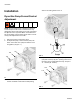
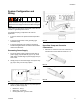
For GLC2200 Controller installations on the side of
the Enclosure (1):
GLC2200 Installation
1. Align the GLC2200 Controller with the pre-drilled
mounting holes on the Enclosure (1) or alternate
mounting surface.
2. Use two screws (not provided) to secure the
GLC2200 controller to the mounting surface.
NOTE: GLC220 installation on the Enclosure (1) is
shown in F
IG. 6.
3. Plug the large connector end (d) of the GLC2200
wiring harness into the GLC2200 as shown in F
IG.
6. The connector can only be plugged into the
GLC2200 one way. The clip should be facing to the
back (or down) when the connector is correctly ori-
ented.
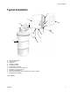
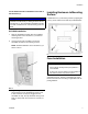
Installing Enclosure to Mounting
Surface
Install Enclosure (1) to mounting surface by aligning the
holes (f) in the enclosure box with the pre-drilled holes.
Fuse Installation
A 6.3 Amp Fuse Kit, 16Y312 is available from Graco.
Discard unused fuses according to applicable local dis-
posal guidelines
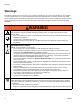
NOTICE
To prevent damaging and/or contaminating the
GLC2200 Controller while pre-drilling the other holes in
the Enclosure (1), do not install the GLC2200 controller
to the side of the Enclosure until all mounting holes are
drilled.
FIG. 6
d
FIG. 7
NOTICE
Fuses are required. To avoid equipment damage:
• Never operate the Dyna-Star pump without a
fuse installed.
• A fuse of the correct voltage must be installed in
line with the power entry to the system.
f
f
f
f